2.5Installing Cable Strain Relief
To prevent load cell or peripheral cable damage from bending and twisting, cable strain reliefs are used in the back of the
1.Remove the three 4 mm x 8 mm panhead screws securing the bracket to the back of the keyboard.
2.Remove rubber strain relief covering the two
3.Route load cell and/or any peripheral device cables through opening in bracket. Connect cables to proper ports.
4.Install rubber strain relief over load cell/ peripheral cables and position into cavity. Gently pull cables to take up any slack.
5.When rubber strain reliefs are securely mounted, reinstall bracket using the three 4 mm x 8 mm panhead screws previously removed.
2.6Pole Mounting Instructions
1.Disconnect AC power cord from the bottom of the scale. Remove platform.
2.Remove the plastic cover from the upper mounting bracket.
NOTE: As a precaution, install load cell setscrew.
3.Turn scale on side.
4.Attach pole mount assembly to base using three 4 mm x 10 mm machine screws (shown in Figure
POLE ASSEMBLY
MOUNT BRACKET
5.Route load cell and peripheral device cables through center of pole mount assembly.
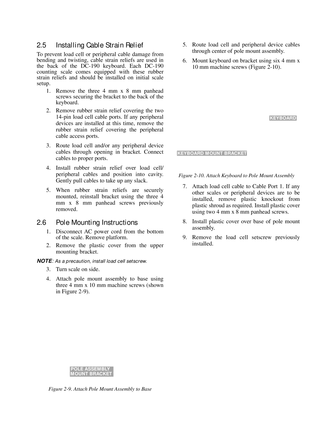
6.Mount keyboard on bracket using six 4 mm x 10 mm machine screws (Figure
![]()
![]() KEYBOARD
KEYBOARD
KEYBOARD MOUNT BRACKET![]()
Figure 2-10. Attach Keyboard to Pole Mount Assembly
7.Attach load cell cable to Cable Port 1. If any other scales or peripheral devices are to be installed, remove plastic knockout from plastic shroud as required. Install plastic cover using two 4 mm x 8 mm panhead screws.
8.Install plastic cover over base of pole mount assembly.
9.Remove the load cell setscrew previously installed.