10.3 Connector Pinouts
The
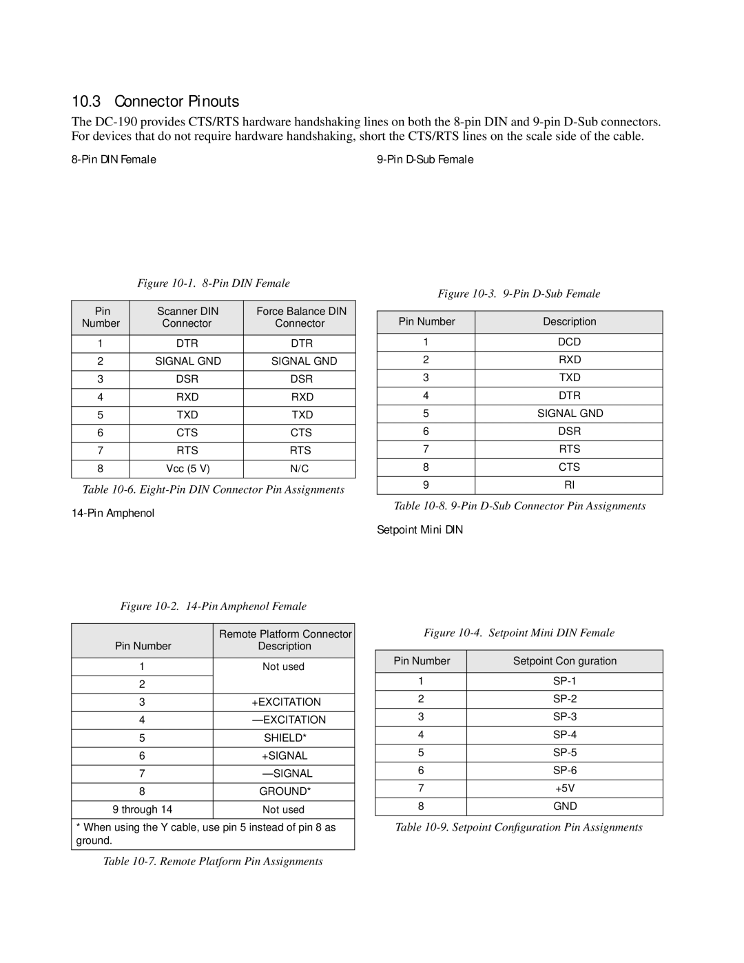
8-Pin DIN Female
Figure 10-1. 8-Pin DIN Female
Pin | Scanner DIN | Force Balance DIN |
Number | Connector | Connector |
|
|
|
1 | DTR | DTR |
|
|
|
2 | SIGNAL GND | SIGNAL GND |
|
|
|
3 | DSR | DSR |
|
|
|
4 | RXD | RXD |
|
|
|
5 | TXD | TXD |
|
|
|
6 | CTS | CTS |
|
|
|
7 | RTS | RTS |
|
|
|
8 | Vcc (5 V) | N/C |
|
|
|
Table
14-Pin Amphenol
Figure 10-2. 14-Pin Amphenol Female
| Remote Platform Connector |
Pin Number | Description |
|
|
1 | Not used |
|
|
2 |
|
|
|
3 | +EXCITATION |
|
|
4 | |
|
|
5 | SHIELD* |
|
|
6 | +SIGNAL |
|
|
7 | |
|
|
8 | GROUND* |
|
|
9 through 14 | Not used |
|
|
* When using the Y cable, use pin 5 instead of pin 8 as ground.
Figure 10-3. 9-Pin D-Sub Female
Pin Number | Description |
|
|
1 | DCD |
|
|
2 | RXD |
|
|
3 | TXD |
|
|
4 | DTR |
|
|
5 | SIGNAL GND |
|
|
6 | DSR |
|
|
7 | RTS |
|
|
8 | CTS |
|
|
9 | RI |
|
|
Table
Setpoint Mini DIN
Figure 10-4. Setpoint Mini DIN Female
Pin Number | Setpoint Configuration |
|
|
1 | |
|
|
2 | |
|
|
3 | |
|
|
4 | |
|
|
5 | |
|
|
6 | |
|
|
7 | +5V |
|
|
8 | GND |
|
|
Table
Table