2.3Powering Up the DC-190
The
2.3.1AC Power Source
To
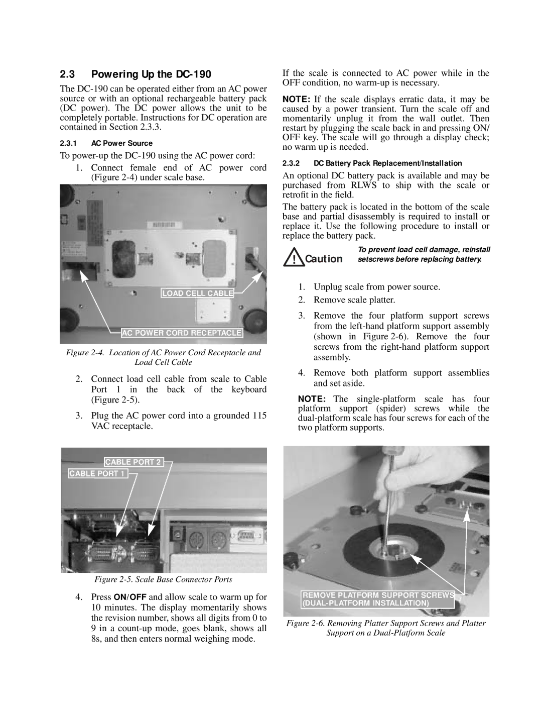
1.Connect female end of AC power cord (Figure
LOAD CELL CABLE![]()
![]()
![]() AC POWER CORD RECEPTACLE
AC POWER CORD RECEPTACLE
Figure 2-4. Location of AC Power Cord Receptacle and
Load Cell Cable
2.Connect load cell cable from scale to Cable Port 1 in the back of the keyboard (Figure
3.Plug the AC power cord into a grounded 115 VAC receptacle.
CABLE PORT 2
CABLE PORT 1 ![]()
![]()
Figure 2-5. Scale Base Connector Ports
4.Press ON/OFF and allow scale to warm up for 10 minutes. The display momentarily shows the revision number, shows all digits from 0 to 9 in a
If the scale is connected to AC power while in the OFF condition, no
NOTE: If the scale displays erratic data, it may be caused by a power transient. Turn the scale off and momentarily unplug it from the wall outlet. Then restart by plugging the scale back in and pressing ON/ OFF key. The scale will go through a display check; no warm up is needed.
2.3.2DC Battery Pack Replacement/Installation
An optional DC battery pack is available and may be purchased from RLWS to ship with the scale or retrofit in the field.
The battery pack is located in the bottom of the scale base and partial disassembly is required to install or replace it. Use the following procedure to install or replace the battery pack.
To prevent load cell damage, reinstall Caution setscrews before replacing battery.
1.Unplug scale from power source.
2.Remove scale platter.
3.Remove the four platform support screws from the
4.Remove both platform support assemblies and set aside.
NOTE: The
REMOVE PLATFORM SUPPORT SCREWS