Digi DC-190 installation manual Scale Setup, Scale Configurations, Spec

Models: DC-190

1 33
Download 33 pages 24.46 Kb
Page 11
Image 11

3.0Scale Setup

This section provides information about attaching scales and serial devices to the DC-190. Information presented describes both physical connections and values that must be specified when configuring the DC-190 (see Section 4.0). If you know what scales and serial devices will be connected to the DC-190, you can use the SPEC Code Worksheets Section 10.1 on page 50 to record these values for later configuration.

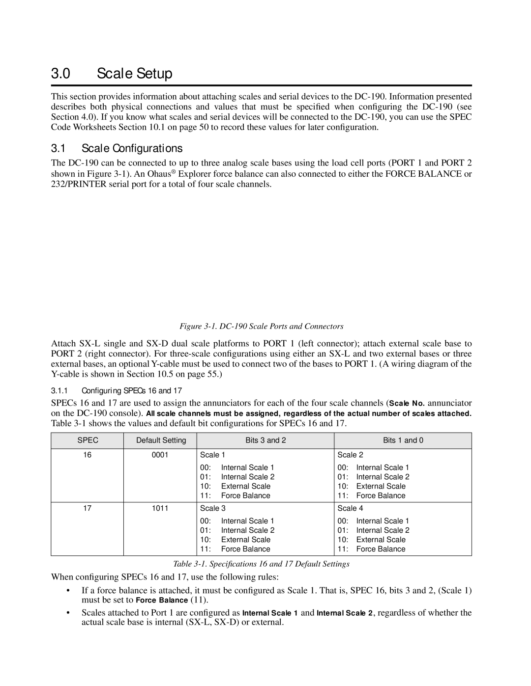
3.1Scale Configurations

The DC-190 can be connected to up to three analog scale bases using the load cell ports (PORT 1 and PORT 2 shown in Figure 3-1). An Ohaus® Explorer force balance can also connected to either the FORCE BALANCE or 232/PRINTER serial port for a total of four scale channels.

PORT 1

PORT 2

Figure 3-1. DC-190 Scale Ports and Connectors

Attach SX-L single and SX-D dual scale platforms to PORT 1 (left connector); attach external scale base to PORT 2 (right connector). For three-scale configurations using either an SX-L and two external bases or three external bases, an optional Y-cable must be used to connect two of the bases to PORT 1. (A wiring diagram of the Y-cable is shown in Section 10.5 on page 55.)

3.1.1Configuring SPECs 16 and 17

SPECs 16 and 17 are used to assign the annunciators for each of the four scale channels (Scale No. annunciator on the DC-190 console). All scale channels must be assigned, regardless of the actual number of scales attached. Table 3-1 shows the values and default bit configurations for SPECs 16 and 17.

SPEC

Default Setting


Bits 3 and 2


Bits 1 and 0


16

0001

Scale 1

Scale 2


00:

Internal Scale 1

00:

Internal Scale 1


01:

Internal Scale 2

01:

Internal Scale 2


10:

External Scale

10:

External Scale


11:

Force Balance

11:

Force Balance


17

1011

Scale 3

Scale 4


00:

Internal Scale 1

00:

Internal Scale 1


01:

Internal Scale 2

01:

Internal Scale 2


10:

External Scale

10:

External Scale


11:

Force Balance

11:

Force Balance


Table 3-1. Specifications 16 and 17 Default Settings

When configuring SPECs 16 and 17, use the following rules:

If a force balance is attached, it must be configured as Scale 1. That is, SPEC 16, bits 3 and 2, (Scale 1) must be set to Force Balance (11).

Scales attached to Port 1 are configured as Internal Scale 1 and Internal Scale 2, regardless of whether the actual scale base is internal (SX-L, SX-D) or external.

Page 11
Image 11
Digi DC-190 installation manual Scale Setup, Scale Configurations, Spec