b. Optical Preamplifier Adjustments
Step |
|
| Action |
| Indicationn |
|
No. |
|
|
|
| ||
|
|
|
|
|
| |
9 |
|
|
|
|
|
|
|
|
| CAT. NO. 97 TEST FILM |
|
|
|
|
|
|
|
| OSCILLOSCOPE TRACE |
|
10 |
|
|
| CAT NO. |
| |
|
|
|
| 222 | Cat. No. |
|
|
|
|
|
| 240A |
|
|
|
|
|
| Proj. 1 |
|
|
|
|
|
| GAIN |
|
|
|
|
|
| Lt |
|
|
|
|
|
| hf | Lt |
|
|
|
|
| GAIN | |
|
|
|
| Lt |
| |
|
|
|
| Rt |
| |
|
|
|
| hf |
| |
|
|
|
| Lt tp |
| |
|
|
|
|
|
| |
|
|
|
|
| Lt | Rt |
|
|
|
|
| signal | |
|
|
|
|
|
| |
|
|
|
|
| present |
|
|
|
|
|
| Rt |
|
|
|
|
| Rt | Rt tp |
|
|
|
|
| GAIN |
| |
|
|
|
|
|
| |
|
|
|
|
| Lt |
|
|
|
|
|
| hf |
|
|
|
|
|
| GAIN |
|
|
|
|
|
| Rt |
|
|
|
|
|
| hf |
|
|
|
|
|
| Proj. 2 |
|
|
|
|
|
| gnd |
|
| L R |
|
|
|
|
|
11 | REPEAT | 8 | AND 9 |
|
|
|
b. Optical Preamplifier Adjustments
Notes
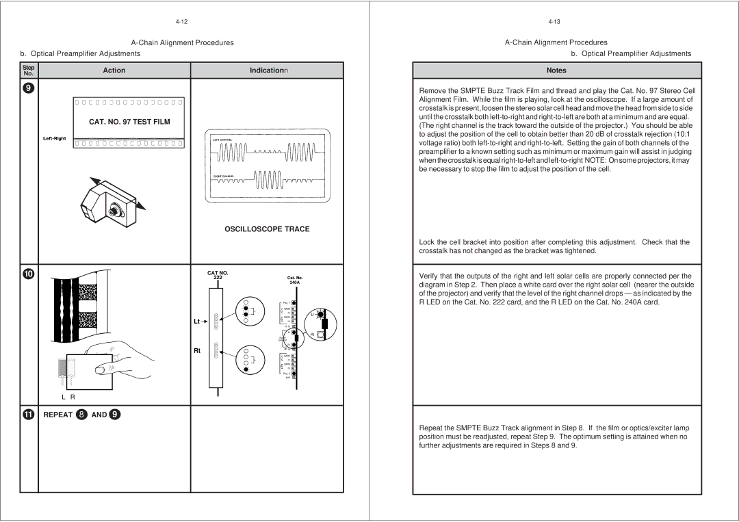
Remove the SMPTE Buzz Track Film and thread and play the Cat. No. 97 Stereo Cell Alignment Film. While the film is playing, look at the oscilloscope. If a large amount of crosstalk is present, loosen the stereo solar cell head and move the head from side to side until the crosstalk both
(The right channel is the track toward the outside of the projector.) You should be able to adjust the position of the cell to obtain better than 20 dB of crosstalk rejection (10:1 voltage ratio) both
Lock the cell bracket into position after completing this adjustment. Check that the crosstalk has not changed as the bracket was tightened.
Verify that the outputs of the right and left solar cells are properly connected per the diagram in Step 2. Then place a white card over the right solar cell (nearer the outside of the projector) and verify that the level of the right channel drops — as indicated by the R LED on the Cat. No. 222 card, and the R LED on the Cat. No. 240A card.
Repeat the SMPTE Buzz Track alignment in Step 8. If the film or optics/exciter lamp position must be readjusted, repeat Step 9. The optimum setting is attained when no further adjustments are required in Steps 8 and 9.