Installation and Alignment Instructions
Model CP65 Cinema Processor
Dolby Laboratories Inc U.S. Headquarters
U.K. European Office
Dolby Laboratories Inc
100 Potrero Avenue San Francisco, CA Telephone
Table of Contents
INITIAL SET-UPAND INSTALLATION
INTRODUCTION
EQUIPMENT REQUIRED
APPENDIX A
APPENDIX B
APPENDIX C
APPENDIX D
INTRODUCTION
CP65
04 Dolby Stereo A-type 05 Dolby Stereo SR
60 Non-sync
Page
1 Dolby Tone and Pink Noise - Cat. No
SECTION EQUIPMENT REQUIRED
2 1kHz, 100% Modulation, Left/Right - Cat. No
TEST FILM
3SMPTE Buzz Track
4Stereo Optical Surround Level - Cat. No
JIFFY
SECTION INITIAL SET-UPAND INSTALLATION
Setting
Voltage
Acceptable
Voltage Range
Cat. No
Cat. No. 242, B-ChainCard
Cat. No. 249, Power Supply Module
J5 J6 J7 J8
Cat. No. 443, Control Logic Card
J3 IN
CP65 Backplane
Standard CP65 or CP65A
In a CP65-300when Cat. No. 300 modules are fitted in place of the normal Cat. No. 350 modules J16 and J18 should be rotated so that the words “Format 42” appears the right way up. With J24 in the “NR” position input signals will be A-typedecoded when the Mag/Aux format is selected. With J24 in the “NO NR” position signals pass through the noise reduction modules but the processing will be turned off. If both of these processing options are required frequently an external switch may be connected to J24
CP65-300
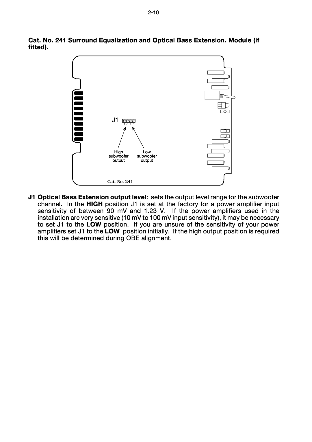
J1 Optical Bass Extension output level sets the output level range for the subwoofer channel. In the HIGH position J1 is set at the factory for a power amplifier input sensitivity of between 90 mV and 1.23 V. If the power amplifiers used in the installation are very sensitive 10 mV to 100 mV input sensitivity, it may be necessary to set J1 to the LOW position. If you are unsure of the sensitivity of your power amplifiers set J1 to the LOW position initially. If the high output position is required this will be determined during OBE alignment
selected projector. Electronic switches select
Card Descriptions
Slot
Card
Two-channelNoise
Reduction Module
2 4 Channel Decoder
7,8,9
Slot
Card
Function
Cat. No
Voltage Setting
International
Fuse
Type
IEC NOTICES
GB F D I E S NL
IMPORTANT SAFETY NOTICE
IMPORTANT - NOTE DE SECURITE
3.Room lighting dimmer controls SCR-TYPE
HUM PROBLEMS
Model CP65
With CP65 FADER turned up and format 04 selected
1. Aligning the A-Chain
SECTION AN OVERVIEW OF THE ALIGNMENT PROCEDURE
2. Aligning the B-Chain
and with a broad range of speakers. Accurate equalization requires the use of standardized acoustic measurement procedures
Many loudspeakers used in theatres are far from ideal and require boosting of the low- and high-frequencyextremes in order to produce an approximation of the standard reference response curve. Bass and treble controls-centeredon the turnover points of typical loudspeakers-liftthe ends of the spectrum without the need for large amounts of narrow- band boost from the third-octavecontrols in the Cat. No. 64 cards. The third-octavecontrols are used for minor adjustments that are required to smooth the frequency response curve
SECTION A-CHAINALIGNMENT
a. Preliminary Procedures
a. Preliminary Procedures Notes
Action
Indication
A-ChainAlignment Procedures
a. Preliminary Procedures
a. Preliminary Procedures Notes
Action
b. Optical Preamplifier Adjustments
b. Optical Preamplifier Adjustments Notes
Action
Indication
A-ChainAlignment Procedures
b. Optical Preamplifier Adjustments
b. Optical Preamplifier Adjustments Notes
Action
L L R R L L R R
CAT NO
b. Optical Preamplifier Adjustments
b. Optical Preamplifier Adjustments Notes
Action
Indicationn
CAT. NO. 97 TEST FILM
REPEAT
OSCILLOSCOPE TRACES
RTA DISPLAY
A-ChainAlignment Procedures
b. Optical Preamplifier Adjustments
12 AND
REPEAT
A-ChainAlignment Procedures
b. Optical Preamplifier Adjustments
CAT NO
FOR PROJECTOR NO. REPEAT 1 →
b. Optical Preamplifier Adjustments
b. Optical Preamplifier Adjustments Notes
c. Magnetic Preamplifier Adjustments
Magnetic Alignment
c. Magnetic Preamplifier Adjustments
A-ChainAlignment Procedures
Magnetic Alignment
SECTION B-CHAINALIGNMENT
a. Setting Room Equalization
a. Setting Room Equalization Notes
bypass
Action
Loudspeakers and Crossovers
a. Setting Room Equalization
a. Setting Room Equalization Notes
Action
bypass
Amplifiers
General
a. Setting Room Equalization
B-ChainAlignment Procedures
a. Setting Room Equalization Notes
Action
Indication
REPEAT
a. Setting Room Equalization
a. Setting Room Equalization Notes
Action
B-ChainAlignment Procedures
a. Setting Room Equalization
a. Setting Room Equalization Notes
Action
Do not adjust
a. Setting Room Equalization
a. Setting Room Equalization Notes
Action
a. Setting Room Equalization
a. Setting Room Equalization Notes
Action
Indication
b. Adjusting L,C,R Gain
b.Adjusting L,C,R Gain
L 14 → 21 R 14 →
22REPEAT
c. Setting Mono Gain
c. Setting Mono Gain Notes
79 dBC
Action
d. Subwoofer Alignment Cat. No
d. Subwoofer Alignment Cat. No. Notes
B-ChainAlignment Procedures
Action
90 dBC
B-ChainAlignment Procedures
d. Subwoofer Alignment Cat. No
Action
FROM
d. Subwoofer Alignment Cat. No
d. Subwoofer Alignment Cat. No
Action
Select format 04 Dolby Stereo A-Type
d. Subwoofer Alignment Cat. No
Action
REPEAT
SAME AS
d. Subwoofer Alignment Cat. No
d. Subwoofer Alignment Cat. No
Action
Re S
e. Surround Equalization Alignment Cat. No
e. Surround Equalization Alignment Cat. No
Action
e. Surround Equalization Alignment Cat. No
Action
Action
e. Surround Equalization Alignment Cat. No
REPEAT
e. Surround Equalization Alignment Cat. No
88 dBC
Action
B-ChainAlignment Procedures
e. Surround Equalization Alignment Cat. No
Action
Indication
f. Adjustment of Surround Delay
Thumbwheel Switch
msec
Setting
g. Adjustment of Bypass Gain
g. Adjustment of Bypass Gain Notes
xx dBC
B-ChainAlignment Procedures
FROM xx dBC -3dB yy dBC
B-ChainAlignment Procedures
g. Adjustment of Bypass Gain
g. Adjustment of Bypass Gain Notes
h. Adjustment of Non-syncGain
h. Adjustment of Non-syncGain Notes
Press the format 60 non sync switch
Action
h. Adjustment of Non-syncGain
h. Adjustment of Non-syncGain Notes
Action
Indication
i. Adjustment of Mono Gain and Equalization
i.Adjustment of Mono Gain and Equalization Notes
5REPEAT PAGE 5-20STEP
B-ChainAlignment Procedures
Press the format 04 Dolby Stereo A-type switch
JIFFY TEST FILM
j. Final Checks
j. Final Checks Notes
SECTION REFERENCE DIAGRAMS
Cat. No. 222 Dual Noise Reduction Module
INPUTS
OUTPUTS
Page
Cat. No. 242 B-ChainFacilities Card
Cat. No. 249 Power Supply Card
Cat. No. 259 Transformer Module
INPUTS
OUTPUTS
Cat. No. 443 Control Logic Card
CP65 POWER DISTRIBUTION TABLE
Cat. No
+24V
+15V
APPENDIX A CHECKING PHASING OF SPEAKERS
Frequency in Hz
5,000
10,000
20,000
1.Operation
APPENDIX C CP65M MONO INSTRUCTIONS
2.Cat. No. 327A Circuit Description
C.2 Schematic Cat. No. 327A
A3C2984 rev
APPENDIX D BACKPLANE CONNECTIONS LIST
CP65 Backplane Connections
Terminal Block TB1
Terminal Block TB2
D connector J18