|
|
|
|
|
|
|
|
|
|
| |
|
|
|
|
|
|
|
|
|
|
|
|
g. Adjustment of Bypass Gain |
| ||||||||||
|
|
|
|
|
|
|
|
|
|
|
|
Step |
|
|
|
| Action | Indication |
| ||||
No. |
|
|
|
|
|
|
|
|
|
|
|
5 | NORMAL BYPASS |
|
| ||||||||
|
|
|
|
|
|
|
|
|
| bypass |
|
|
|
|
|
|
|
|
|
|
|
| |
|
|
|
|
|
|
|
|
|
|
| |
|
|
|
|
|
|
|
|
|
|
| |
|
|
|
|
|
|
|
|
|
| (switch behind panel) |
|
|
|
|
|
|
|
|
|
|
|
|
|
|
|
|
|
|
|
|
|
|
|
|
|
|
|
|
|
|
|
|
|
|
|
|
|
6
FROM 4
xx dBC -3 dB
yy dBC
g. Adjustment of Bypass Gain
Notes
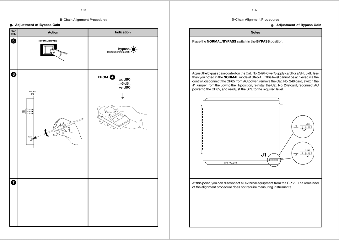
Place the NORMAL/BYPASS switch in the BYPASS position.
Adjust the bypass gain control on the Cat. No. 249 Power Supply card for a SPL 3 dB less than you noted in the NORMAL mode at Step 4. If this level cannot be achieved via the control, disconnect the CP65 from AC power, remove the Cat. No. 249 card, switch the J1 jumper from the Low to the Hi position, reinstall the Cat. No. 249 card, reconnect AC power to the CP65, and readjust the SPL to the required level.
power supply status
Cat. No.
249
24V
15V
15V
Dolby ![]()
![]()
bypass
gain
➝
FF |
|
|
|
|
| 3 | |
O |
|
|
|
|
|
| |
| 80 |
| 0 |
|
| 40 | 0 |
| 7 | 0 | 50 |
| |||
|
|
| 6 |
|
| ||
Low
High
J1
CAT. NO. 249
7
At this point, you can disconnect all external equipment from the CP65. The remainder of the alignment procedure does not require measuring instruments.
