b. Optical Preamplifier Adjustments
Step | Action | Indication | |
No. | |||
|
| ||
|
|
|
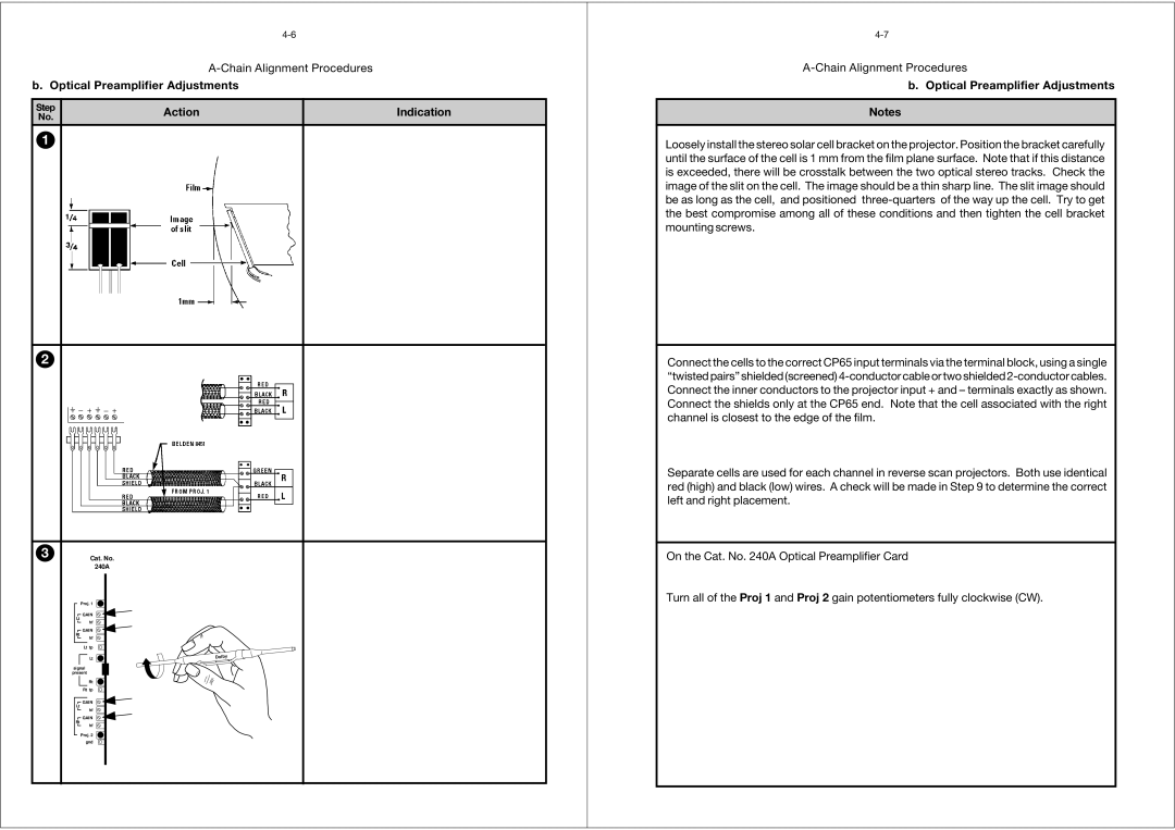
1
2
3Cat. No.
240A
Proj. 1
![]() GAIN Lt
GAIN Lt
hf
![]() GAIN
GAIN
Rt
hf
Lt tp
Lt
signal
present
Rt
Rt tp
![]() GAIN Lt
GAIN Lt
hf
![]() GAIN Rt
GAIN Rt
hf
Proj. 2 gnd
b. Optical Preamplifier Adjustments
Notes
Loosely install the stereo solar cell bracket on the projector. Position the bracket carefully until the surface of the cell is 1 mm from the film plane surface. Note that if this distance is exceeded, there will be crosstalk between the two optical stereo tracks. Check the image of the slit on the cell. The image should be a thin sharp line. The slit image should be as long as the cell, and positioned
Connect the cells to the correct CP65 input terminals via the terminal block, using a single “twisted pairs” shielded (screened)
Separate cells are used for each channel in reverse scan projectors. Both use identical red (high) and black (low) wires. A check will be made in Step 9 to determine the correct left and right placement.
On the Cat. No. 240A Optical Preamplifier Card
Turn all of the Proj 1 and Proj 2 gain potentiometers fully clockwise (CW).