8 Appendices
8.1Tables of alarms and events
8.1.1 Table of alarms
List of time dated alarms
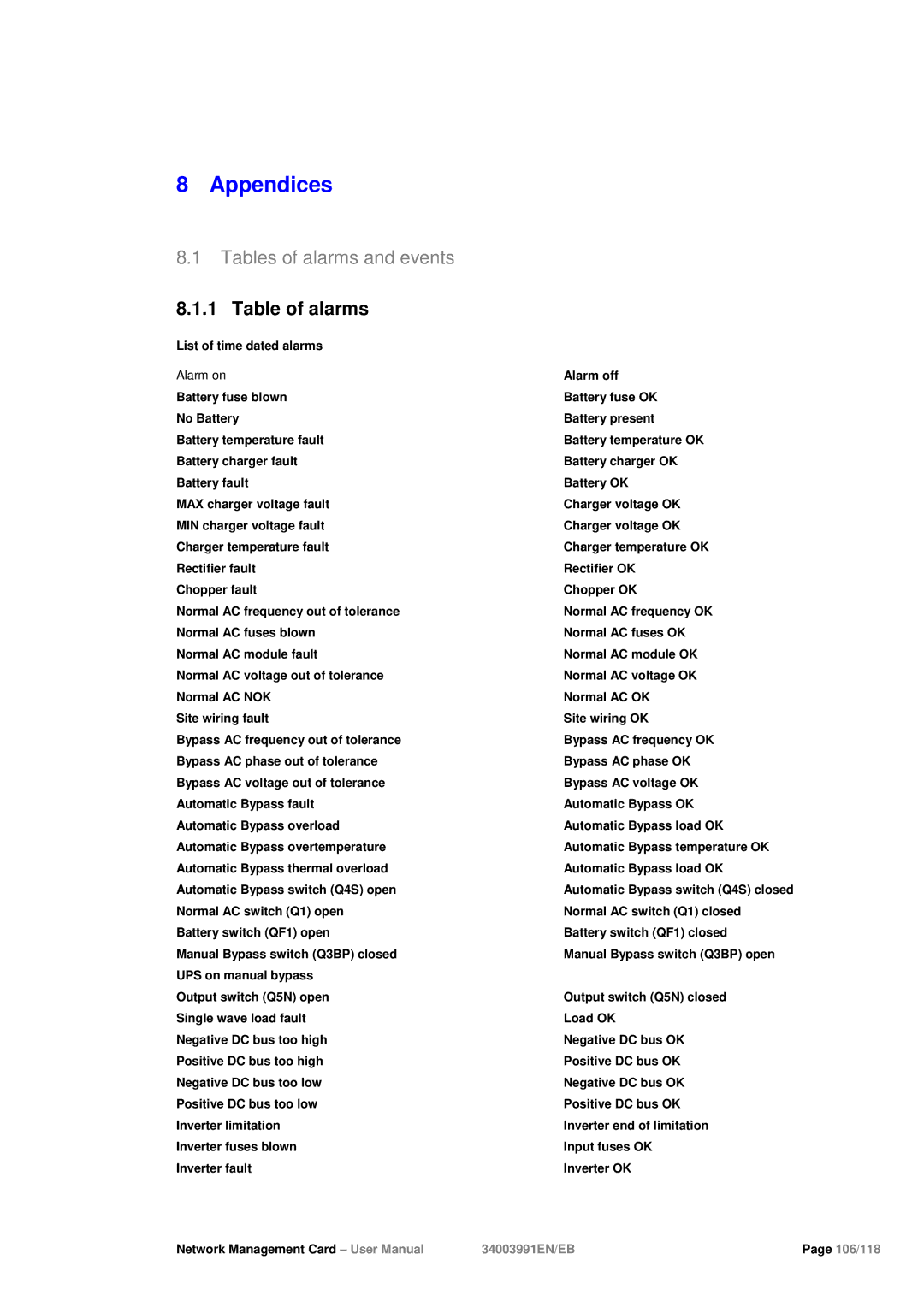
Alarm on
Battery fuse blown
No Battery
Battery temperature fault
Battery charger fault
Battery fault
MAX charger voltage fault
MIN charger voltage fault
Charger temperature fault
Rectifier fault
Chopper fault
Normal AC frequency out of tolerance Normal AC fuses blown
Normal AC module fault
Normal AC voltage out of tolerance Normal AC NOK
Site wiring fault
Bypass AC frequency out of tolerance Bypass AC phase out of tolerance Bypass AC voltage out of tolerance Automatic Bypass fault
Automatic Bypass overload Automatic Bypass overtemperature Automatic Bypass thermal overload Automatic Bypass switch (Q4S) open Normal AC switch (Q1) open Battery switch (QF1) open
Manual Bypass switch (Q3BP) closed UPS on manual bypass
Output switch (Q5N) open
Single wave load fault
Negative DC bus too high
Positive DC bus too high
Negative DC bus too low
Positive DC bus too low
Inverter limitation
Inverter fuses blown
Inverter fault
Alarm off
Battery fuse OK
Battery present
Battery temperature OK
Battery charger OK
Battery OK
Charger voltage OK
Charger voltage OK
Charger temperature OK
Rectifier OK
Chopper OK
Normal AC frequency OK
Normal AC fuses OK
Normal AC module OK
Normal AC voltage OK
Normal AC OK
Site wiring OK
Bypass AC frequency OK Bypass AC phase OK Bypass AC voltage OK Automatic Bypass OK Automatic Bypass load OK Automatic Bypass temperature OK Automatic Bypass load OK Automatic Bypass switch (Q4S) closed Normal AC switch (Q1) closed Battery switch (QF1) closed
Manual Bypass switch (Q3BP) open
Output switch (Q5N) closed
Load OK
Negative DC bus OK
Positive DC bus OK
Negative DC bus OK
Positive DC bus OK
Inverter end of limitation
Input fuses OK
Inverter OK
Network Management Card – User Manual | 34003991EN/EB | Page 106/118 |
