AUDIO –
AUDIO + | SHIELD |
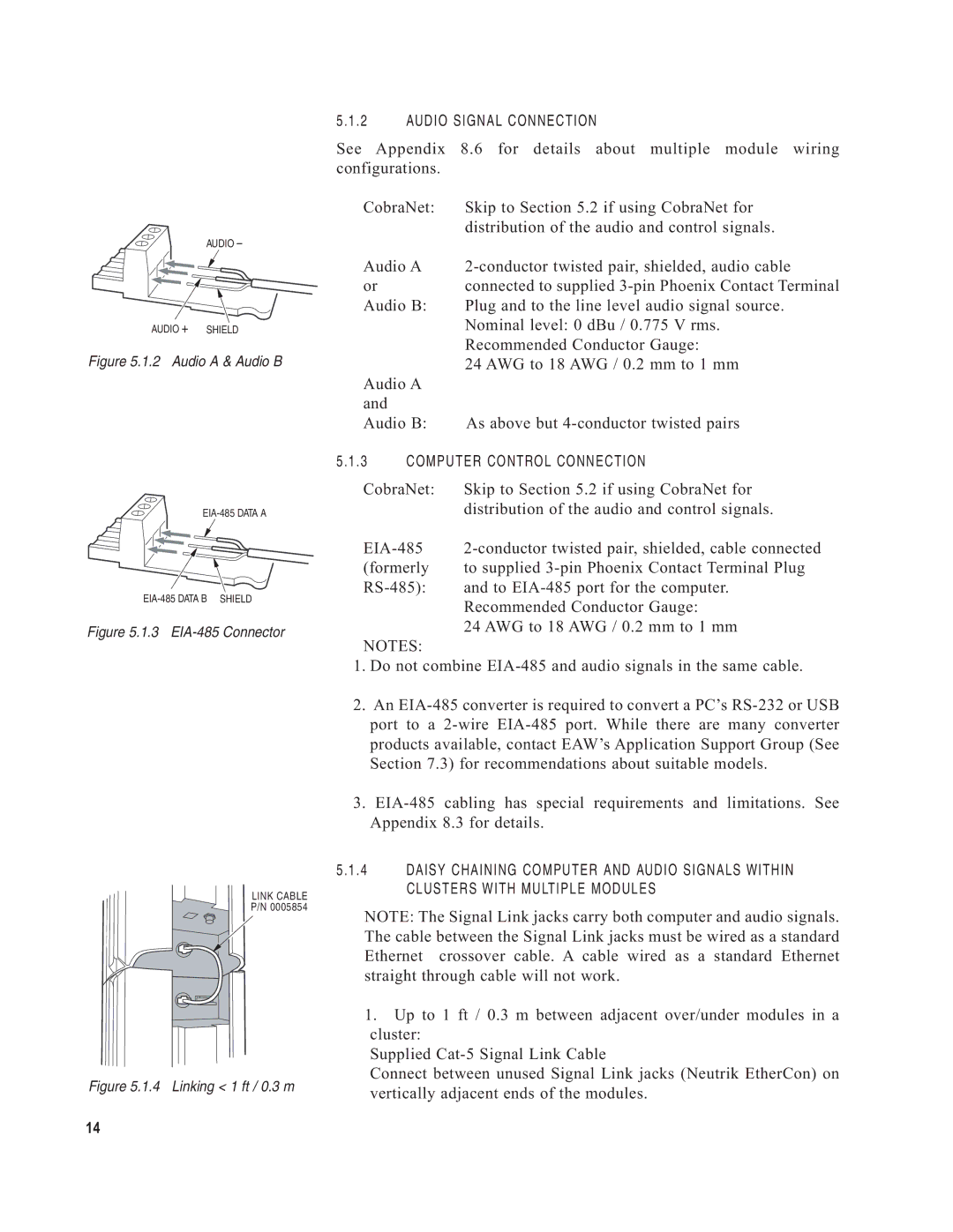
Figure 5.1.2 Audio A & Audio B
Figure 5.1.3 EIA-485 Connector
LINK CABLE
P/N 0005854
Figure 5.1.4 Linking < 1 ft / 0.3 m
5.1.2 AUDIO SIGNAL CONNECTION
See Appendix 8.6 for details about multiple module wiring configurations.
CobraNet: | Skip to Section 5.2 if using CobraNet for | |
|
| distribution of the audio and control signals. |
Audio A | ||
or |
| connected to supplied |
Audio B: | Plug and to the line level audio signal source. | |
|
| Nominal level: 0 dBu / 0.775 V rms. |
|
| Recommended Conductor Gauge: |
|
| 24 AWG to 18 AWG / 0.2 mm to 1 mm |
Audio A |
| |
and |
|
|
Audio B: | As above but | |
5.1.3 | COMPUTER CONTROL CONNECTION | |
CobraNet: | Skip to Section 5.2 if using CobraNet for | |
|
| distribution of the audio and control signals. |
(formerly | to supplied | |
and to | ||
|
| Recommended Conductor Gauge: |
|
| 24 AWG to 18 AWG / 0.2 mm to 1 mm |
NOTES: |
| |
1.Do not combine
2.An
3.
5.1.4 DAISY CHAINING COMPUTER AND AUDIO SIGNALS WITHIN CLUSTERS WITH MULTIPLE MODULES
NOTE: The Signal Link jacks carry both computer and audio signals. The cable between the Signal Link jacks must be wired as a standard Ethernet crossover cable. A cable wired as a standard Ethernet straight through cable will not work.
1.Up to 1 ft / 0.3 m between adjacent over/under modules in a cluster:
Supplied
Connect between unused Signal Link jacks (Neutrik EtherCon) on vertically adjacent ends of the modules.
14