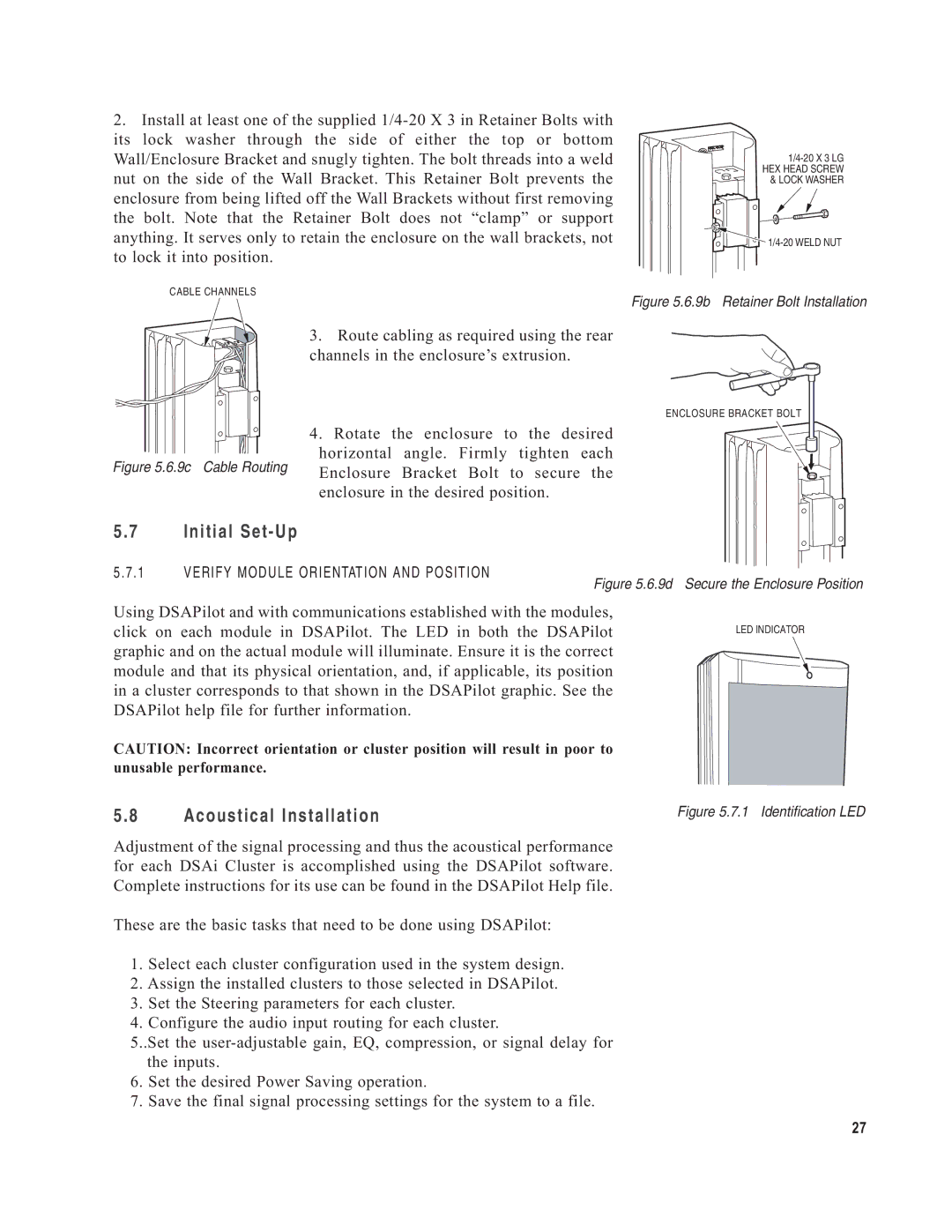
2.Install at least one of the supplied
CABLE CHANNELS
3. Route cabling as required using the rear channels in the enclosure’s extrusion.
Figure 5.6.9b Retainer Bolt Installation
Figure 5.6.9c Cable Routing
5.7 Initial Set-Up
ENCLOSURE BRACKET BOLT
4. Rotate the enclosure to the desired horizontal angle. Firmly tighten each Enclosure Bracket Bolt to secure the enclosure in the desired position.
5.7.1 VERIFY MODULE ORIENTATION AND POSITION
Figure 5.6.9d Secure the Enclosure Position
Using DSAPilot and with communications established with the modules, click on each module in DSAPilot. The LED in both the DSAPilot graphic and on the actual module will illuminate. Ensure it is the correct module and that its physical orientation, and, if applicable, its position in a cluster corresponds to that shown in the DSAPilot graphic. See the DSAPilot help file for further information.
CAUTION: Incorrect orientation or cluster position will result in poor to unusable performance.
LED INDICATOR
5.8 Acoustical Installation
Figure 5.7.1 Identification LED
Adjustment of the signal processing and thus the acoustical performance for each DSAi Cluster is accomplished using the DSAPilot software. Complete instructions for its use can be found in the DSAPilot Help file.
These are the basic tasks that need to be done using DSAPilot:
1.Select each cluster configuration used in the system design.
2.Assign the installed clusters to those selected in DSAPilot.
3.Set the Steering parameters for each cluster.
4.Configure the audio input routing for each cluster.
5..Set the
6.Set the desired Power Saving operation.
7.Save the final signal processing settings for the system to a file.
27