3.6 Physical Installation
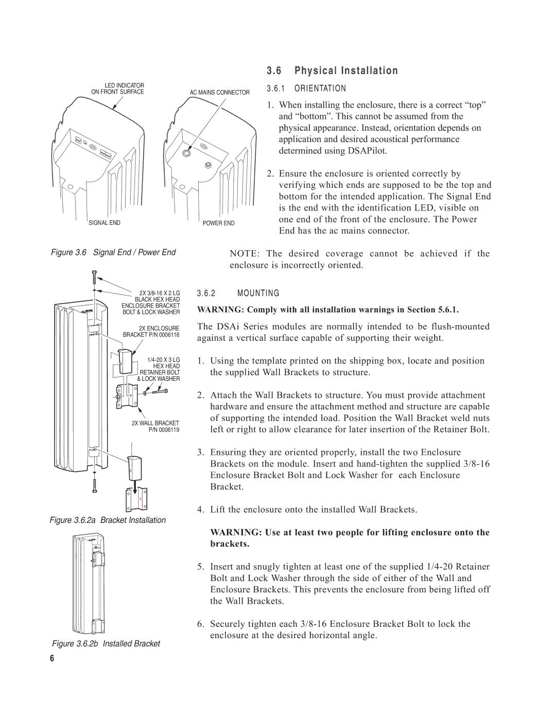
LED INDICATOR ON FRONT SURFACE
SIGNAL END
AC MAINS CONNECTOR
POWER END
3.6.1 ORIENTATION
1.When installing the enclosure, there is a correct “top” and “bottom”. This cannot be assumed from the physical appearance. Instead, orientation depends on application and desired acoustical performance determined using DSAPilot.
2.Ensure the enclosure is oriented correctly by verifying which ends are supposed to be the top and bottom for the intended application. The Signal End is the end with the identification LED, visible on one end of the front of the enclosure. The Power End has the ac mains connector.
Figure 3.6 Signal End / Power End
2X
BLACK HEX HEAD ENCLOSURE BRACKET BOLT & LOCK WASHER
2X ENCLOSURE ![]() BRACKET P/N 0006118
BRACKET P/N 0006118
HEX HEAD RETAINER BOLT & LOCK WASHER
2X WALL BRACKET P/N 0006119
Figure 3.6.2a Bracket Installation
Figure 3.6.2b Installed Bracket
NOTE: The desired coverage cannot be achieved if the enclosure is incorrectly oriented.
3.6.2 MOUNTING
WARNING: Comply with all installation warnings in Section 5.6.1.
The DSAi Series modules are normally intended to be
1.Using the template printed on the shipping box, locate and position the supplied Wall Brackets to structure.
2.Attach the Wall Brackets to structure. You must provide attachment hardware and ensure the attachment method and structure are capable of supporting the intended load. Position the Wall Bracket weld nuts left or right to allow clearance for later insertion of the Retainer Bolt.
3.Ensuring they are oriented properly, install the two Enclosure Brackets on the module. Insert and
4.Lift the enclosure onto the installed Wall Brackets.
WARNING: Use at least two people for lifting enclosure onto the brackets.
5.Insert and snugly tighten at least one of the supplied
6.Securely tighten each
6