WALL
DSA
SUPPLIED
WALL
BRACKETS
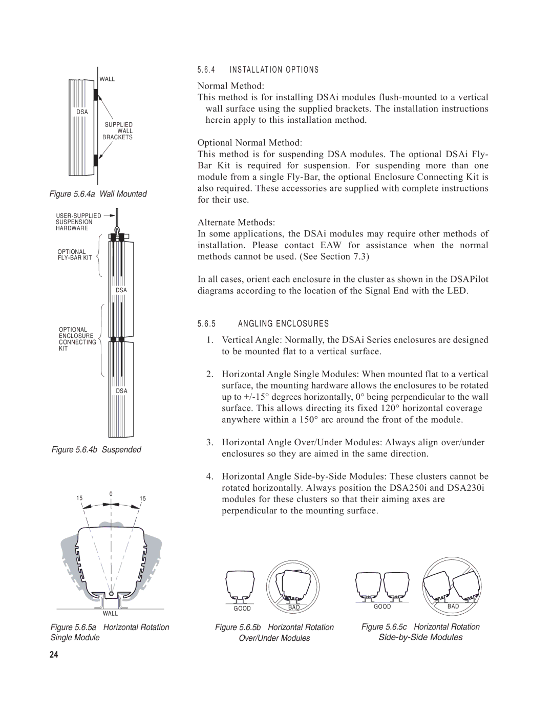
Figure 5.6.4a Wall Mounted
SUSPENSION
HARDWARE
OPTIONAL
DSA
OPTIONAL
ENCLOSURE
CONNECTING
KIT
DSA
Figure 5.6.4b Suspended
0
1515
5 . 6 . 4 | I N S TA L L AT I O N O P T I O N S |
Normal Method:
This method is for installing DSAi modules
Optional Normal Method:
This method is for suspending DSA modules. The optional DSAi Fly- Bar Kit is required for suspension. For suspending more than one module from a single
Alternate Methods:
In some applications, the DSAi modules may require other methods of installation. Please contact EAW for assistance when the normal methods cannot be used. (See Section 7.3)
In all cases, orient each enclosure in the cluster as shown in the DSAPilot diagrams according to the location of the Signal End with the LED.
5.6.5 ANGLING ENCLOSURES
1.Vertical Angle: Normally, the DSAi Series enclosures are designed to be mounted flat to a vertical surface.
2.Horizontal Angle Single Modules: When mounted flat to a vertical surface, the mounting hardware allows the enclosures to be rotated up to
3.Horizontal Angle Over/Under Modules: Always align over/under enclosures so they are aimed in the same direction.
4.Horizontal Angle
WALL | GOOD | BAD | GOOD | BAD |
|
|
|
| |
Figure 5.6.5a Horizontal Rotation | Figure 5.6.5b | Horizontal Rotation | Figure 5.6.5c | Horizontal Rotation |
Single Module | Over/Under Modules | |||
24
