5.3.3 SUPERVISORY CIRCUITS
While there are a number of possible supervisory circuits, the normal method is to use the relay contacts to connect or disconnect power to an annunciator. This can be a light, audible alarm, computer interface, or other indicator. A light is used in the example diagrams.
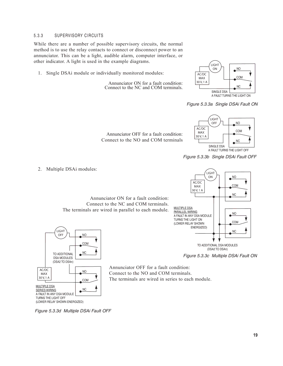
1. Single DSAi module or individually monitored modules:
Annunciator ON for a fault condition:
Connect to the NC and COM terminals.
AC/DC
MAX
30 V, 1 A
LIGHT
ONNO
COM
NC
SINGLE DSA
A FAULT TURNS THE LIGHT ON
Figure 5.3.3a Single DSAi Fault ON
Annunciator OFF for a fault condition: Connect to the NO and COM terminals
AC/DC
MAX
30 V, 1 A
LIGHT
OFFNO
COM
NC
SINGLE DSA
A FAULT TURNS THE LIGHT OFF
Figure 5.3.3b Single DSAi Fault OFF
2. Multiple DSAi modules:
Annunciator ON for a fault condition: Connect to the NC and COM terminals.
The terminals are wired in parallel to each module.
LIGHT
OFFNO
| COM |
TO ADDITIONAL | NC |
| |
DSA MODULES |
|
(DSA2 TO DSAn) |
|
|
| LIGHT |
| |
|
| ON | NO | |
|
|
|
| |
| AC/DC |
| COM | |
| MAX |
| ||
| 30 V, 1 A |
|
| |
|
|
| NC | |
MULTIPLE DSA | ||||
| ||||
PARALLEL WIRING | NO | |||
A FAULT IN ANY DSA MODULE | ||||
| ||||
TURNS THE LIGHT ON | COM | |||
(LOWER RELAY SHOWN | ||||
| ||||
| ENERGIZED) |
| ||
|
|
| NC | |
TO ADDITIONAL DSA MODULES
(DSA2 TO DSAn)
Figure 5.3.3c Multiple DSAi Fault ON
AC/DC | NO | |
MAX | ||
| ||
30 V, 1 A | COM | |
| ||
|
MULTIPLE DSA
SERIES WIRINGNC A FAULT IN ANY DSA MODULE TURNS THE LIGHT OFF
(LOWER RELAY SHOWN ENERGIZED)
Annunciator OFF for a fault condition: Connect to the NO and COM terminals.
The terminals are wired in series to each module.
Figure 5.3.3d Multiple DSAi Fault OFF
19