The orientations are shown in the DSAPilot graphics. When activated by the DSAPilot software, this LED can be used to verify both the correct
5.6.3 MULTIPLE MODULES AND CLUSTER CONFIGURATIONS
CAUTION: Only clusters included in DSAPilot may be used. Any other configurations will result in poor to unusable performance.
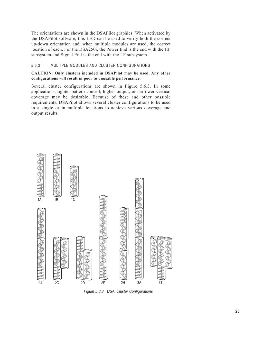
Several cluster configurations are shown in Figure 5.6.3. In some applications, tighter pattern control, higher output, or narrower vertical coverage may be desirable. Because of these and other possible requirements, DSAPilot allows several cluster configurations to be used in a single or in multiple locations to achieve various coverage and output results.
1A 1B 1C
2A | 2C | 2D | 2F | 2H | 3A | 3T |
Figure 5.6.3 DSAi Cluster Configurations
23