Connecting Pin Assignments
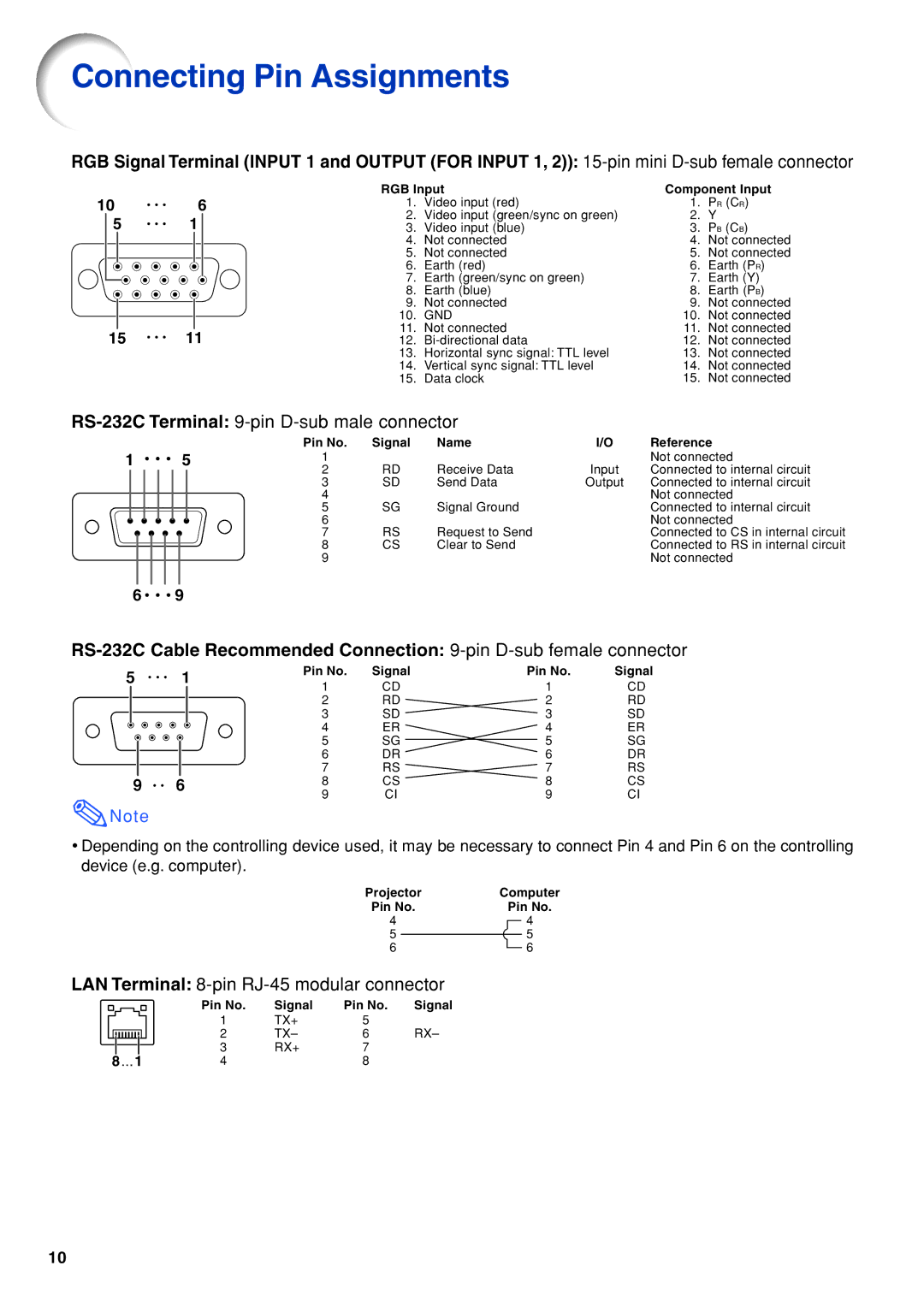
RGB Signal Terminal (INPUT 1 and OUTPUT (FOR INPUT 1, 2)):
10 |
| 6 | |||
| 5 | 1 |
| ||
|
|
|
|
|
|
|
|
|
|
|
|
|
|
|
|
|
|
15 | 11 |
RGB Input | Component Input | ||
1. | Video input (red) | 1. | PR (CR) |
2. | Video input (green/sync on green) | 2. | Y |
3. | Video input (blue) | 3. | PB (CB) |
4. | Not connected | 4. | Not connected |
5. | Not connected | 5. | Not connected |
6. | Earth (red) | 6. | Earth (PR) |
7. | Earth (green/sync on green) | 7. | Earth (Y) |
8. | Earth (blue) | 8. | Earth (PB) |
9. | Not connected | 9. | Not connected |
10. | GND | 10. | Not connected |
11. | Not connected | 11. | Not connected |
12. | 12. | Not connected | |
13. | Horizontal sync signal: TTL level | 13. | Not connected |
14. | Vertical sync signal: TTL level | 14. | Not connected |
15. | Data clock | 15. | Not connected |
RS-232C Terminal: 9-pin D-sub male connector
|
|
|
|
|
|
|
|
|
| Pin No. | Signal | Name | I/O | Reference |
1 |
|
|
|
|
| 5 | 1 |
|
|
| Not connected | |||
|
|
|
|
|
|
|
|
|
| 2 | RD | Receive Data | Input | Connected to internal circuit |
|
|
|
|
|
|
|
|
|
| 3 | SD | Send Data | Output | Connected to internal circuit |
|
|
|
|
|
|
|
|
|
| 4 |
|
|
| Not connected |
|
|
|
|
|
|
|
|
|
| 5 | SG | Signal Ground |
| Connected to internal circuit |
|
|
|
|
|
|
|
|
|
| 6 |
|
|
| Not connected |
|
|
|
|
|
|
|
|
|
|
|
|
| ||
|
|
|
|
|
|
|
|
|
| 7 | RS | Request to Send |
| Connected to CS in internal circuit |
|
|
|
|
|
|
|
|
|
| 8 | CS | Clear to Send |
| Connected to RS in internal circuit |
|
|
|
|
|
|
|
|
|
| 9 |
|
|
| Not connected |
|
|
|
|
|
|
|
|
|
|
|
|
|
| |
6 |
|
|
|
| 9 |
|
|
|
|
|
| |||
5 | 1 | Pin No. | Signal | Pin No. | Signal | |
1 | CD | 1 | CD | |||
|
| |||||
|
| 2 | RD | 2 | RD | |
|
| 3 | SD | 3 | SD | |
|
| 4 | ER | 4 | ER | |
|
| 5 | SG | 5 | SG | |
|
| 6 | DR | 6 | DR | |
|
| 7 | RS | 7 | RS | |
9 | 6 | 8 | CS | 8 | CS | |
|
| 9 | CI | 9 | CI |
![]() Note
Note
•Depending on the controlling device used, it may be necessary to connect Pin 4 and Pin 6 on the controlling device (e.g. computer).
Projector | Computer | ||||||
Pin No. |
| Pin No. | |||||
4 |
|
|
|
|
| 4 | |
5 |
|
|
|
|
| 5 | |
|
|
|
|
| |||
6 |
|
|
|
|
| 6 | |
LAN Terminal:
|
|
|
|
|
|
|
| Pin No. | Signal | Pin No. | Signal |
|
|
|
|
|
|
|
| ||||
|
|
|
|
|
|
|
| 1 | TX+ | 5 |
|
|
|
|
|
|
|
|
| 2 | TX– | 6 | RX– |
|
|
|
|
|
|
|
| ||||
|
|
|
|
|
|
|
| 3 | RX+ | 7 |
|
8 ... 1 | 4 |
| 8 |
| |||||||
10