3000 specifications
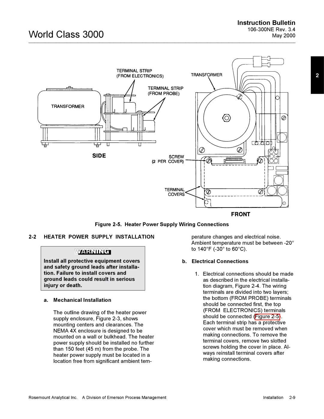
The Emerson 3000 is a cutting-edge control system designed to enhance the efficiency, reliability, and precision of industrial operations. Employed across various sectors such as oil and gas, pharmaceutical, food and beverage, and power generation, the Emerson 3000 has gained recognition for its robustness and versatility.One of the main features of the Emerson 3000 is its advanced process control capability. With integrated control algorithms, it can optimize complex processes in real-time, resulting in significant improvements in production rates and reduced operational costs. The system's predictive analytics capabilities enable operators to anticipate equipment failures and maintenance needs, allowing for proactive management and minimizing downtime.
The Emerson 3000 features a modular architecture, providing flexibility for scaling and customization. Operators can easily tailor the system to fit specific application needs, whether it requires additional control loops or integration with other systems. This adaptability is particularly beneficial for facilities planning for future expansions or modifications.
Another technology highlight of the Emerson 3000 is its seamless integration with the latest Internet of Things (IoT) advancements. The system is designed to communicate effectively with a variety of smart devices and sensors, harnessing data to create insightful analytics that drive operational excellence. This connectivity empowers businesses to leverage big data for improved decision-making and increased agility.
Additionally, the Emerson 3000 incorporates state-of-the-art cybersecurity measures to safeguard critical data and operations. With built-in security protocols and regular updates, the system protects against emerging cyber threats, ensuring the integrity of the control network.
User experience is also a focal point of the Emerson 3000. The intuitive graphical user interface presents complex data in a user-friendly format, making it easier for operators to monitor system performance and respond to alerts quickly. This ease of use contributes to enhanced safety and operational efficiency.
In summary, the Emerson 3000 represents a fusion of advanced process control, modular design, IoT connectivity, robust cybersecurity, and user-centric interface, making it an ideal choice for industries seeking to enhance their operational performance while adapting to ever-evolving technological landscapes.

