MODEL | SECTION 2.0 |
| INSTALLATION |
2.6 POWER MODULE INSTALLATION
The section describes the procedure for installation of the power module (part number
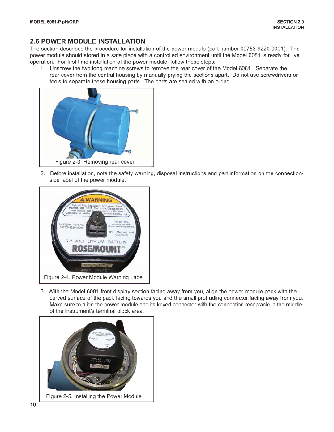
1.Unscrew the two long machine screws to remove the rear cover of the Model 6081. Separate the rear cover from the central housing by manually prying the sections apart. Do not use screwdrivers or tools to separate these housing parts. The parts are sealed with an
Figure 2-3. Removing rear cover
2.Before installation, note the safety warning, disposal instructions and part information on the connection- side label of the power module.
Figure 2-4. Power Module Warning Label
3.With the Model 6081 front display section facing away from you, align the power module pack with the curved surface of the pack facing towards you and the small protruding connector facing away from you. Make sure to align the power module and its keyed connector with the connection receptacle in the middle of the instrument’s terminal block area.
Figure 2-5. Installing the Power Module
10
