AXP1406/AXP1600 Subsystem Ipmi
Contact Address
Contents
6.6
OEM Sensors
Contents
List of Tables
List of Tables
85 Sensor No 0x06 FRU 5 Hotswap
115
About this Manual
Overview of Contents
Conventions
Abbreviations
Summary of Changes
Comments and Suggestions
Introduction
Standard Ipmi Commands
Global Ipmi Commands
Supported Global Ipmi Commands
Supported BMC Device and Messaging Commands
BMC WatchDog Timer Commands
BMC Device and Messaging Commands
Supported BMC WatchDog Timer Commands
Event Commands
Chassis Device Commands
PEF and Alerting Commands
Supported Sensor Device Commands
Sensor Device Commands
SDR Device Commands
FRU Device Commands
SEL Device Commands
12 Supported Serial/Modem Device Commands
LAN Device Commands
Serial/Modem Device Commands
11 Supported LAN Device Commands
13 Supported Picmg 3.0 Commands
Picmg 3.0 Commands
14 OEM Command Summary
Emerson and Pigeon Point OEM Commands
15 Get Shelf Configuration Record Cmd =
17 Set FRU Extracted Cmd =
16 Shelf Manager Switchover Cmd =
Page
Total Power Consumption for AXP 1406 and AXP1600 Shelves
Total Power Consumption
SAM Physical FRU Information
SAM1000 Physical Shelf Manager
Physical Shelf Manager FRU Data, AXP1406
Physical Shelf Manager FRU Data, AXP1600
SAM Physical Power Configuration
Power Configuration
Keying
Sensor Overview
Sensor Overview
Voltage Sensors
SAM Physical Shelf Manager Analog Sensors
Sensor No Vbat
Sensor No +12 V Voltage
Sensor No 3.3 V Voltage
Sensor No +1.8
Temperature Sensors
Sensor No MAX6656 INT@1A
Sensor No MAX6656 EXT1@1A
10 Sensor No MAX6656 EXT2@1A
SAM Module Discrete Sensors
12 Sensor No Ipmb Link
Hot Swap Sensor
Ipmb Link Sensor
11 Sensor No FRU 0 Hotswap
13 Sensor No PEM a
PEM a Sensor
14 Sensor No PEM B
PEM B Sensor
15 Sensor No NSC a AXP1600 Only
16 Sensor No NSC B AXP1600 Only
18 Sensor No 12 V B Valid
AXP Backplane ID Sensor
6.6 +12 V B Valid Sensor
17 Sensor No AXP Backplane ID
19 Sensor No 12 V a Valid
6.7 +12 V a Valid Sensor
21 Sensor No Post Results
Fault Event Sensor
20 Sensor No Fault Event
Post Results Sensor
22 Sensor No Shelf FRU Info
Shelf FRU Info Sensor
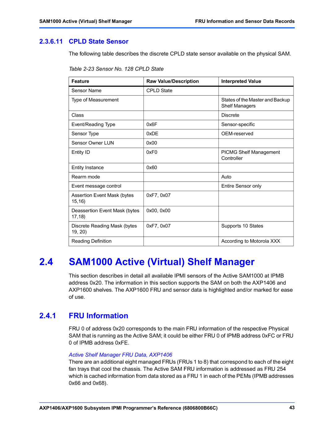
23 Sensor No Cpld State
SAM1000 Active Virtual Shelf Manager
FRU Information
Cpld State Sensor
Active Shelf Manager FRU Data, AXP1600
Active Shelf Manager FRU Data, AXP1406
FRU Information FRU Information and Sensor Data Records
Active Shelf Manager FRU Data, AXP1600
FRU Information FRU Information and Sensor Data Records
1.3 SAM1000 Shelf Manager FRU Data
Upper Fan Tray Locations, AXP1406
Fan Tray FRU Data, AXP1406
Fan Tray FRUs 1,2, and 3 Data
Fan Tray FRUs 7 and 8 Data
Fan Tray FRUs 4, 5, and 6 Data
Upper Fan Tray Locations, AXP1600
Fan Tray FRU Data, AXP1600
Lower Fan Tray Locations, AXP1600
Fan Tray FRUs 1, 2, and 3 Data, AXP1600
Fan Tray FRUs 4, 5, and 6 Data, AXP1600
Fan Tray FRUs 7, 8 and 9 Data, AXP1600
Active SAM1000 Sensor Overview
24 SAM1000 Active Power Configuration
25 Active SAM1000 Sensor Overview
Hotswap FRU9 Hotswap
System Event
25 Active SAM1000 Sensor Overview
25 Active SAM1000 Sensor Overview
27 Sensor No 0x8E FT 1 Fan
Active SAM1000 Analog Sensors
Fan Speed Sensors
26 Sensor No 0x8D FT 1 Fan
29 Sensor No 0x90 FT2 Fan
28 Sensor No 0x8F FT 2 Fan
31 Sensor No 0x92 FT 3 Fan
30 Sensor No 0x91 FT 3 Fan
33 Sensor No 0x94 FT 4 Fan
32 Sensor No 0x93 FT 4 Fan
35 Sensor No 0x96 FT 5 Fan
34 Sensor No 0x95 FT 5 Fan
37 Sensor No 0x98 FT 6 Fan
36 Sensor No 0x97 FT 6 Fan
39 Sensor No 0x9A FT 7 Fan
38 Sensor No 0x99 FT 7 Fan
41 Sensor No 0x9C FT 8 Fan
40 Sensor No 0x9B FT 8 Fan
42 Sensor No 0x9D FT 9 Fan 1, AXP1600
43 Sensor No 0x9E FT 9 Fan 2, AXP1600
Fan Voltage Sensors
44 Sensor No 0xAB FT 1 Fan 1 12
46 Sensor No 0xAD FT 1 Fan 2 12
45 Sensor No 0xAC FT 1 Fan 1 VBias
47 Sensor No 0xAE FT 1 Fan 2 VBias
49 Sensor No 0xB0 FT 2 Fan 1 VBias
48 Sensor No 0xAF FT 2 Fan 1 12
51 Sensor No 0xB2 FT 2 Fan 2 VBias
50 Sensor No 0xB1 FT 2 Fan 2 12
52 Sensor No 0xB3 FT 3 Fan 1 12
54 Sensor No 0xB5 FT 3 Fan 2 12
53 Sensor No 0xB4 FT 3 Fan 1 VBias
56 Sensor No 0xB7 FT 4 Fan 1 12
55 Sensor No 0xB6 FT 3 Fan 2 VBias
57 Sensor No 0xB8 FT 4 Fan 1 VBias
59 Sensor No 0xBA FT 4 Fan 2 VBias
58 Sensor No 0xB9 FT 4 Fan 2 12
61 Sensor No 0xBC FT 5 Fan 1 VBias
60 Sensor No 0xBB FT 5 Fan 1 12
62 Sensor No 0xBD FT 5 Fan 2 12
64 Sensor No 0xBF FT 6 Fan 1 12
63 Sensor No 0xBE FT 5 Fan 2 VBias
66 Sensor No 0xC1 FT 6 Fan 2 12
65 Sensor No 0xC0 FT 6 Fan 1 VBias
67 Sensor No 0xC2 FT 6 Fan 2 VBias
69 Sensor No 0xC4 FT 7 Fan 1 VBias
68 Sensor No 0xC3 FT 7 Fan 1 +12V
71 Sensor No 0xC6 FT 7 Fan 2 VBias
70 Sensor No 0xC5 FT 7 Fan 2 12
72 Sensor No 0xC7 FT 8 Fan 1 12
74 Sensor No 0xC9 FT 8 Fan 2 12
73 Sensor No 0xC8 FT 8 Fan 1 VBias
75 Sensor No 0xCA FT 8 Fan 2 VBias
77 Sensor No 0xCC FT 9 Fan 1 VBias, AXP1600
76 Sensor No 0xCB FT 9 Fan 1 12 V, AXP1600
79 Sensor No 0xCE FT 9 Fan 2 VBias, AXP1600
78 Sensor No 0xCD FT 9 Fan 2 12 V, AXP1600
SAM Active Shelf Manager Discrete Sensors
80 Sensor No 0x00 FRU 0 Hotswap
Hot Swap Sensors
81 Sensor No 0x02 FRU 1 Hotswap
83 Sensor No 0x04 FRU 3 Hotswap
82 Sensor No 0x03 FRU 2 Hotswap
85 Sensor No 0x06 FRU 5 Hotswap
84 Sensor No 0x05 FRU 4 Hotswap
FRU 6 Hotswap
86 Sensor No 0x07 FRU 6 Hotswap
88 Sensor No 0x09 FRU 8 Hotswap
87 Sensor No 0x08 FRU 7 Hotswap
90 Sensor No 0x20 Fault Event Sensor
Shm Fault Event Sensor
89 Sensor No 0x0A FRU 9 HOTSWAP, AXP1600
91 Sensor No 0x0B Ipmb Link
93 Sensor No 0x0D Ipmb Link
92 Sensor No 0x0C Ipmb Link
95 Sensor No 0x0F Ipmb Link
94 Sensor No 0x0E Ipmb Link
96 Sensor No 0x10 Ipmb Link
98 Sensor No 0x12 Ipmb Link
97 Sensor No 0x11 Ipmb Link
100 Sensor No 0x14 Ipmb Link
99 Sensor No 0x14 Ipmb Link
101 Sensor No 0x15 Ipmb Link
103 Sensor No 0x17 Ipmb Link
102 Sensor No 0x16 Ipmb Link
104 Sensor No 0x18 Ipmb Link
106 Sensor No 0x1A Ipmb Link 16, AXP1600
105 Sensor No 0x19 Ipmb Link 15, AXP1600
108 Sensor No 0x1C Ipmb Link 18, AXP1600
107 Sensor No 0x1B Ipmb Link
109 Sensor No 0x1D Ipmb Link 19, AXP1600
111 Sensor No 0x1F Ipmb Link 21, AXP1600
110 Sensor No 0x1E Ipmb Link 20, AXP1600
112 Sensor No 0x83 Telco Alarms
Telco Alarm Sensor
114 Sensor No 0x85 System Event
BMC Watchdog Sensor
System Event
113 Sensor No 0x84 BMC Watchdog
115 Sensor No 0xDC Fan Tray
Fan Tray Presence Sensor
117 Sensor No 0xDE Fan Tray
116 Sensor No 0xDD Fan Tray
119 Sensor No 0xE0 Fan Tray
118 Sensor No 0xDF Fan Tray
121 Sensor No 0xE2 Fan Tray
120 Sensor No 0xE1 Fan Tray
123 Sensor No 0xE4 Fan Tray 9, AXP1600
122 Sensor No 0xE3 Fan Tray
124 Sensor No 0xE6 FT 1 -48 V Fuse
Fan Tray -48 V Fuse Sensor
126 Sensor No 0xE9 FT 4 -48 V Fuse
125 Sensor No 0xE7 FT 2 -48 V Fuse
128 Sensor No 0xEA FT 5 -48 V Fuse
127 Sensor No 0xE8 FT 3 -48 V Fuse
130 Sensor No 0xEC FT 7 -48 V Fuse
129 Sensor No 0xEB FT 6 -48 V Fuse
132 Sensor No 0xEE FT9 -48 V Fuse, AXP1600
131 Sensor No 0xED FT 8 -48 V Fuse
PEM FRU Information
Power Entry Module Sensor Data Records
Value Description
133 Power Configuration for PEMs
Power Entry Module Analog Sensors
Power Entry Module Sensor Overview
134 Ipmi Sensors on the PEM
136 Sensor No +8
135 Sensor No +3.3
138 Sensor No +48.0 V Feed
137 Sensor No +12 V Backplane
139 Sensor No +7.5 V PEM
141 Sensor No +8 V PEM Feed
140 Sensor No +8 V PEM Feed
142 Sensor No +12 V Current
Current Sensor
144 Sensor #0, Hot Swap
Power Entry Module Discrete Sensors
Temperature Sensor
143 Sensor No DS75 Temp
145 Sensor #1, Ipmb Physical
146 Sensor #5, CB
Circuit Breaker State Sensors
147 Sensor #6 CB
149 Sensor No CB
148 Sensor No CB
150 Sensor No CB
OEM Sensors
Telco Alarms Pigeon Point OEM
Post Results Emerson OEM
AXP Backplane ID Emerson OEM
FT -48 V Fuse Emerson OEM
Shelf FRU Info Emerson OEM
Shm Fault Classes
Shm Fault Event Emerson OEM
Cooling Management in Abnormal Operation Mode
Cooling Management in Normal Operation Mode
Adaptive Adjustment of the Minimum Fan Level
Figure A-1 Cooling Algorithm
LED
FRU State Management
Command to Down by 7221
Page
Table B-1 Emerson Newtork Power Embedded Computing Documents
Emerson Network Power Embedded Computing Documents
Table B-2 Manufacturers Documents
Related Specifications
Table B-3 Related Specifications
Manufacturers’ Documents