Table 3-3 - Switch SW2 (2-5), Output Rate Of Change
|
|
|
|
|
|
|
|
| Nominal |
| ||||
|
|
|
|
|
|
|
|
| Rate Of Change, ±15% |
| ||||
|
|
|
|
|
|
|
|
|
|
|
|
|
| |
| Close | Close | Close | Close | 1.8 Min. Full Scale Travel | |||||||||
| Close | Close | Close | Open |
| 5.5 Min. Full Scale Travel | ||||||||
| Close | Close | Open |
| Close |
| 11.0 Min. Full Scale Travel | |||||||
| Close | Close | Open | Open |
| 16.5 Min. Full Scale Travel | ||||||||
| Close | Open |
| Close |
| Close | 21.9 Min. Full Scale Travel | |||||||
| Close | Open |
| Open |
| Close |
| 32.9 Min. Full Scale Travel | ||||||
| Close | Open |
| Open |
| Open |
| 38.3 Min. Full Scale Travel | ||||||
| Open |
| Close |
| Close | Open |
| 43.8 Min. Full Scale Travel | ||||||
| Open |
| Close |
| Open |
| Open |
| 60.3 Min. Full Scale Travel | |||||
| Open |
| Open |
| Close |
| Close |
| 65.85 Min. Full Scale Travel | |||||
| Open |
| Open |
| Close |
| Open |
| 69.4 Min. Full Scale Travel | |||||
3.7 ANALOG FAILURE MODES (Fail Hold & Fail Zero)
Analog models have an "Analog Fault Detector" feature which, when selected by jumpers on the Termination Board, provides a selection of two failure modes, Fail Hold and fail Zero. In the "Fail Hold" mode, the Analog Fault will stop the stepper motor at the last pressure output value prior to the loss of the analog input signal. Note that the Guard terminals are not available for external usage in this mode. The Fault Detector trip point for this mode is factory set at 0.8 volts which corresponds to
In the alternate "Fail Zero" mode, the Guard terminals are available for use with an external signal. In this mode, the analog input signal is “enabled” by a signal at the Guard terminal. If the input drops to zero while the Guard signal remains TRUE, the output will also go to zero.
The selection of either failure mode is accomplished via two jumpers, W1 and W2. These jumpers are located on the Termination Board as shown in Figure
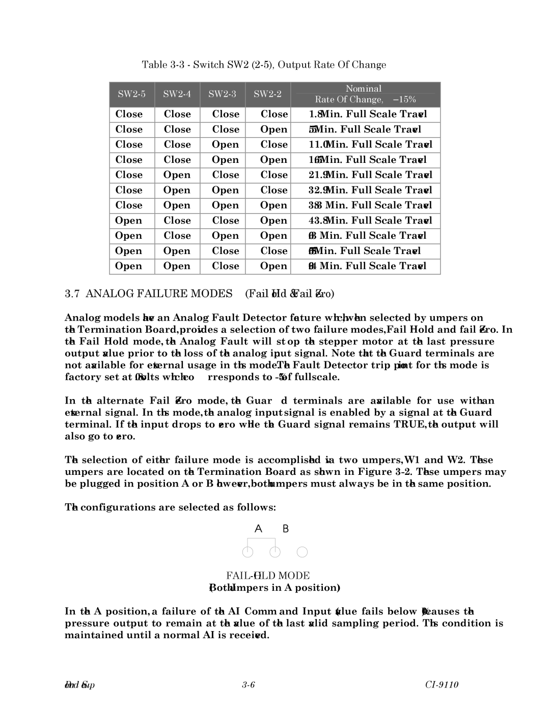
The configurations are selected as follows:
FAIL-HOLD MODE
(Both Jumpers in A position)
In the "A" position, a failure of the AI Command Input (value fails below 0%) causes the pressure output to remain at the value of the last valid sampling period. This condition is maintained until a normal AI is received.
Board Setup |