2.3.3 Line Size
For most installations 1/4 inch pipe or tubing is satisfactory. However, if the input or output lines run a great distance, the response lag time may become objectionable. In these instances the use of 3/8 inch tubing is recommended.
2.3.4 Venting
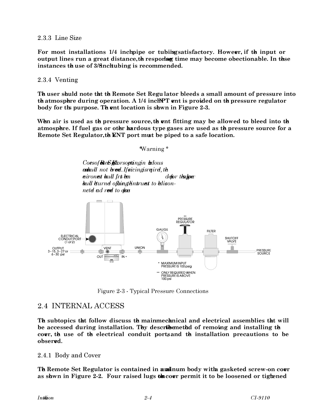
The user should note that the Remote Set Regulator bleeds a small amount of pressure into the atmosphere during operation. A 1/4 inch NPT vent is provided on the pressure regulator body for this purpose. The vent location is shown in Figure
When air is used as the pressure source, the vent fitting may be allowed to bleed into the atmosphere. If fuel gas or other hazardous type gases are used as the pressure source for a Remote Set Regulator, the VENT port must be piped to a safe location.
** Warning **
Covers of Remote Set Regulators operating in hazardous areas should not be removed. If servicing is required, the environment should first be made safe or the supply power should be turned off, allowing the instrument to be discon- nected and removed to a safe area.
Figure 2-3 - Typical Pressure Connections
2.4 INTERNAL ACCESS
The subtopics that follow discuss the main mechanical and electrical assemblies that will be accessed during installation. They describe the method of removing and installing the cover, the use of the electrical conduit ports, and the installation precautions to be observed.
2.4.1 Body and Cover
The Remote Set Regulator is contained in a aluminum body with a gasketed
Installation |