2.2Locate the Wireless client bridge and Inline Power Injector Ports
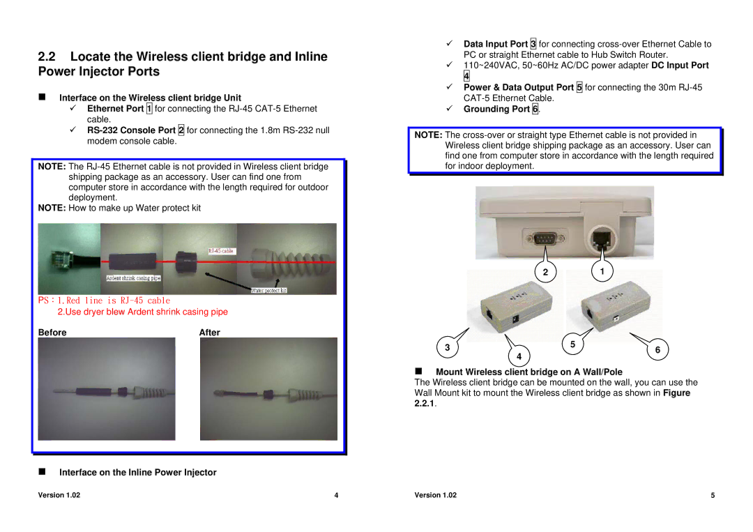
Interface on the Wireless client bridge Unit
9Ethernet Port 1 for connecting the
9
NOTE: The
NOTE: How to make up Water protect kit
PS:1.Red line is
2.Use dryer blew Ardent shrink casing pipe
Before | After |
Interface on the Inline Power Injector
9Data Input Port 3 for connecting
9110~240VAC, 50~60Hz AC/DC power adapter DC Input Port 4
9Power & Data Output Port 5 for connecting the 30m
9Grounding Port 6.
NOTE: The
21
3 | 4 | 5 | 6 |
| |||
|
|
|
Mount Wireless client bridge on A Wall/Pole
The Wireless client bridge can be mounted on the wall, you can use the Wall Mount kit to mount the Wireless client bridge as shown in Figure 2.2.1.
Version 1.02 | 4 | Version 1.02 | 5 |
