Connecting to the Network
c.Verify that the cabling being used is Category 5 UTP with an impedance between 85 and 111 ohms. If the port is to operate at 100 Mbps, category 5 cabling must be used.
d.Verify that the device at the other end of the twisted pair segment is on, and properly connected to the segment.
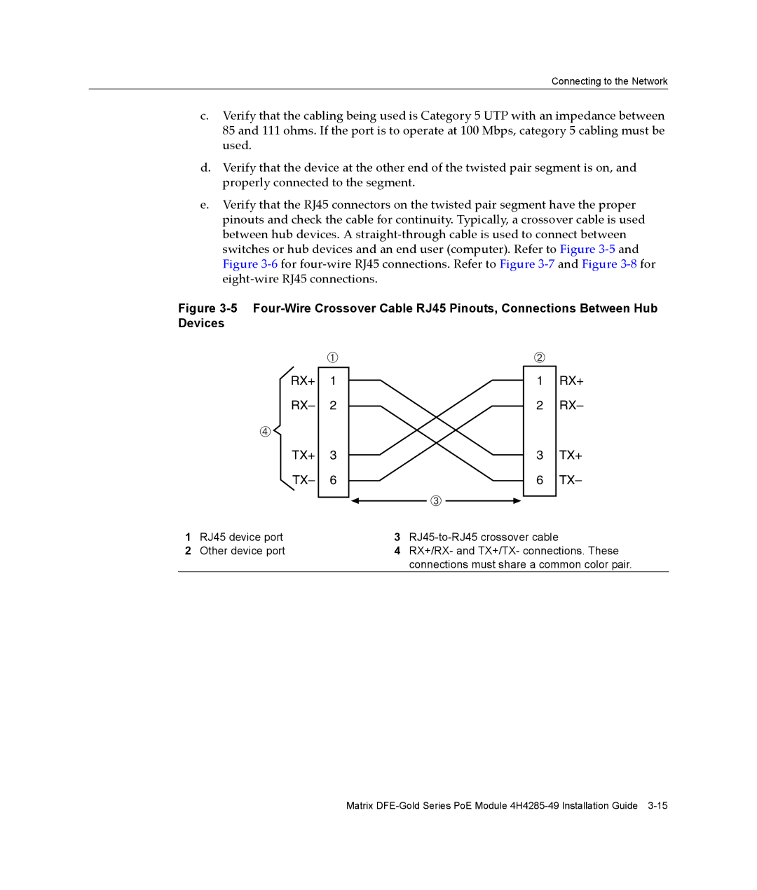
e.Verify that the RJ45 connectors on the twisted pair segment have the proper pinouts and check the cable for continuity. Typically, a crossover cable is used between hub devices. A straight‐through cable is used to connect between switches or hub devices and an end user (computer). Refer to Figure 3‐5 and Figure 3‐6 for four‐wire RJ45 connections. Refer to Figure 3‐7 and Figure 3‐8 for eight‐wire RJ45 connections.
Figure 3-5 Four-Wire Crossover Cable RJ45 Pinouts, Connections Between Hub Devices
| À |
|
|
RX+ | 1 |
RX– | 2 |
à |
|
TX+ | 3 |
TX– | 6 |
|
|
1RJ45 device port
2Other device port
Á
1 RX+
2 RX–
3 TX+
6 TX–
Â
3RJ45-to-RJ45 crossover cable
4RX+/RX- and TX+/TX- connections. These connections must share a common color pair.
Matrix