Connecting to the Network
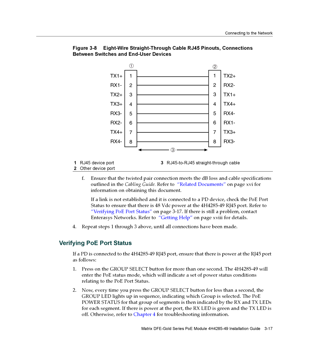
Figure 3-8 Eight-Wire Straight-Through Cable RJ45 Pinouts, Connections Between Switches and End-User Devices
À
TX1+ 1
RX1- 2
TX2+ 3
TX3+ 4
RX3- 5
RX2- 6
TX4+ 7
RX4- 8
Â
Á
1TX2+
2 RX2-
3 TX1+
4 TX4+
5 RX4-
6 RX1-
7 TX3+
8 RX3-
1 RJ45 device port | 3 |
2Other device port
f.Ensure that the twisted pair connection meets the dB loss and cable specifications outlined in the Cabling Guide. Refer to “Related Documents” on page xvi for information on obtaining this document.
If a link is not established and it is connected to a PD device, check the PoE Port Status to ensure that there is 48 Vdc power at the 4H4285‐49 RJ45 port. Refer to “Verifying PoE Port Status” on page 3‐17. If there is still a problem, contact Enterasys Networks. Refer to “Getting Help” on page xviii for details.
4.Repeat steps 1 through 3 above, until all connections have been made.
Verifying PoE Port Status
If a PD is connected to the 4H4285‐49 RJ45 port, ensure that there is power at the RJ45 port as follows:
1.Press on the GROUP SELECT button for more than one second. The 4H4285‐49 will enter the PoE status mode, which will indicate a set of power status conditions relating to the PoE Port Status.
2.Now, every time you press the GROUP SELECT button for less than a second, the GROUP LED lights up in sequence, indicating which Group is selected. The PoE POWER STATUS for that group of segments is then indicated by the RX and TX LEDs for each segment. If there is power at the port, the RX LED is green and the TX LED is off. Otherwise, refer to Chapter 4 for troubleshooting information.
Matrix