Installing and Removing a Power Supply
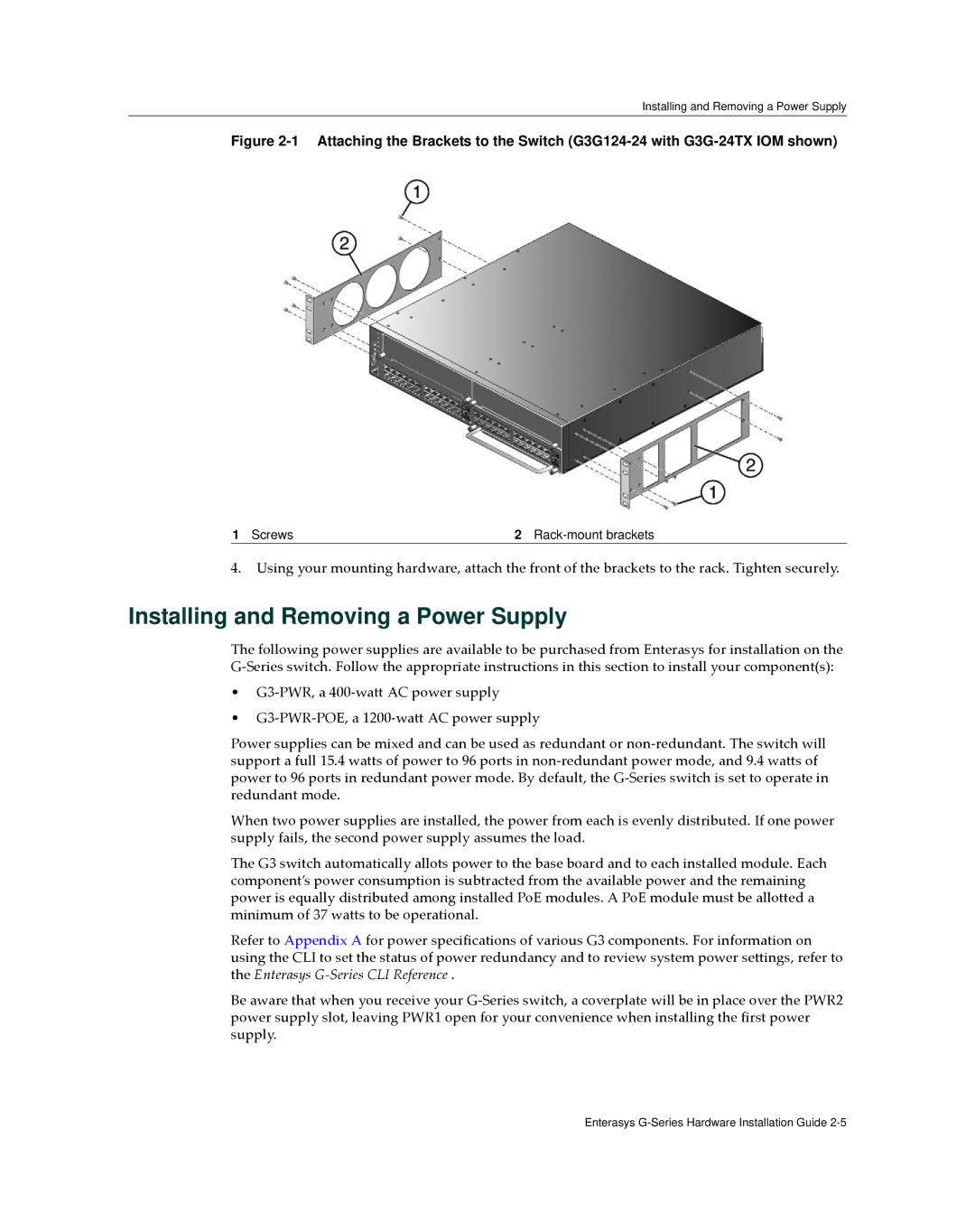
Figure 2-1 Attaching the Brackets to the Switch (G3G124-24 with G3G-24TX IOM shown)
1 Screws | 2 |
4.Using your mounting hardware, attach the front of the brackets to the rack. Tighten securely.
Installing and Removing a Power Supply
The following power supplies are available to be purchased from Enterasys for installation on the G‐Series switch. Follow the appropriate instructions in this section to install your component(s):
•G3‐PWR, a 400‐watt AC power supply
•G3‐PWR‐POE, a 1200‐watt AC power supply
Power supplies can be mixed and can be used as redundant or non‐redundant. The switch will support a full 15.4 watts of power to 96 ports in non‐redundant power mode, and 9.4 watts of power to 96 ports in redundant power mode. By default, the G‐Series switch is set to operate in redundant mode.
When two power supplies are installed, the power from each is evenly distributed. If one power supply fails, the second power supply assumes the load.
The G3 switch automatically allots power to the base board and to each installed module. Each component’s power consumption is subtracted from the available power and the remaining power is equally distributed among installed PoE modules. A PoE module must be allotted a minimum of 37 watts to be operational.
Refer to Appendix A for power specifications of various G3 components. For information on using the CLI to set the status of power redundancy and to review system power settings, refer to the Enterasys G‐Series CLI Reference .
Be aware that when you receive your G‐Series switch, a coverplate will be in place over the PWR2 power supply slot, leaving PWR1 open for your convenience when installing the first power supply.
Enterasys
