Checking the LEDs
Checking the LEDs
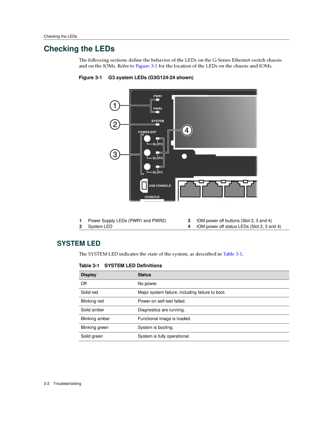
The following sections define the behavior of the LEDs on the G‐Series Ethernet switch chassis and on the IOMs. Refer to Figure 3‐1 for the location of the LEDs on the chassis and IOMs.
Figure 3-1 G3 system LEDs (G3G124-24 shown)
1 | Power Supply LEDs (PWR1 and PWR2) | 3 | IOM power off buttons (Slot 2, 3 and 4) |
2 | System LED | 4 | IOM power off status LEDs (Slot 2, 3 and 4) |
SYSTEM LED
The SYSTEM LED indicates the state of the system, as described in Table 3‐1.
Table 3-1 SYSTEM LED Definitions
Display | Status |
|
|
Off | No power. |
|
|
Solid red | Major system failure, including failure to boot. |
|
|
Blinking red | Power on |
|
|
Solid amber | Diagnostics are running. |
|
|
Blinking amber | Functional image is loaded. |
|
|
Blinking green | System is booting. |
|
|
Solid green | System is fully operational. |
|
|