Installing and Removing a Power Supply
Power Supply Planning
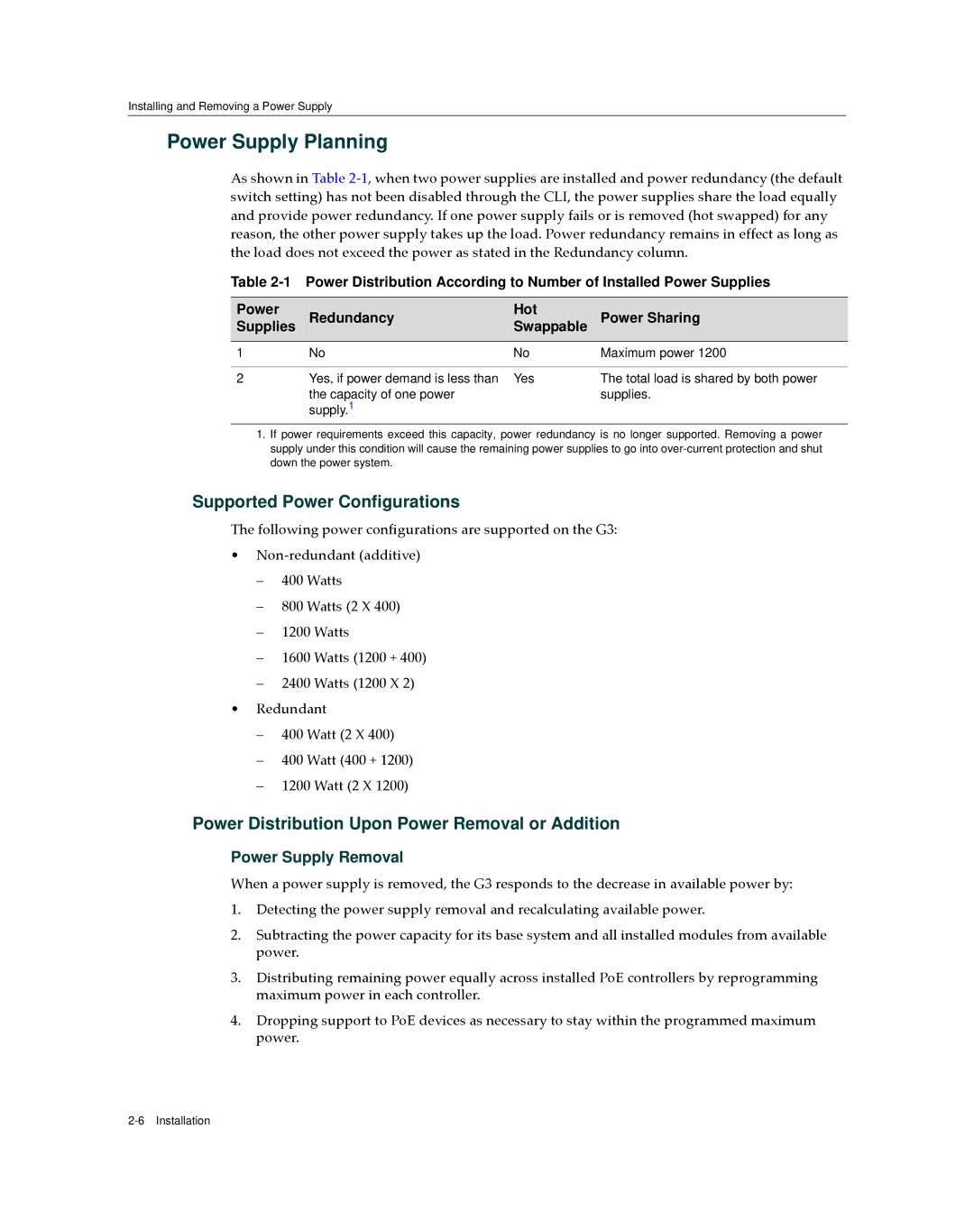
As shown in Table 2‐1, when two power supplies are installed and power redundancy (the default switch setting) has not been disabled through the CLI, the power supplies share the load equally and provide power redundancy. If one power supply fails or is removed (hot swapped) for any reason, the other power supply takes up the load. Power redundancy remains in effect as long as the load does not exceed the power as stated in the Redundancy column.
Table
Power | Redundancy | Hot | Power Sharing |
Supplies | Swappable | ||
|
|
|
|
1 | No | No | Maximum power 1200 |
|
|
|
|
2 | Yes, if power demand is less than | Yes | The total load is shared by both power |
| the capacity of one power |
| supplies. |
| supply.1 |
|
|
1.If power requirements exceed this capacity, power redundancy is no longer supported. Removing a power supply under this condition will cause the remaining power supplies to go into
Supported Power Configurations
The following power configurations are supported on the G3:
•Non‐redundant (additive)
–400 Watts
–800 Watts (2 X 400)
–1200 Watts
–1600 Watts (1200 + 400)
–2400 Watts (1200 X 2)
•Redundant
–400 Watt (2 X 400)
–400 Watt (400 + 1200)
–1200 Watt (2 X 1200)
Power Distribution Upon Power Removal or Addition
Power Supply Removal
When a power supply is removed, the G3 responds to the decrease in available power by:
1.Detecting the power supply removal and recalculating available power.
2.Subtracting the power capacity for its base system and all installed modules from available power.
3.Distributing remaining power equally across installed PoE controllers by reprogramming maximum power in each controller.
4.Dropping support to PoE devices as necessary to stay within the programmed maximum power.