Connecting to the Network
5.When you are ready to begin configuring the G‐Series Ethernet switch, use the procedures in “Completing the Installation” on page 2‐20 to power on the switch and boot the software. You will perform initial setup by entering CLI commands on the management console.
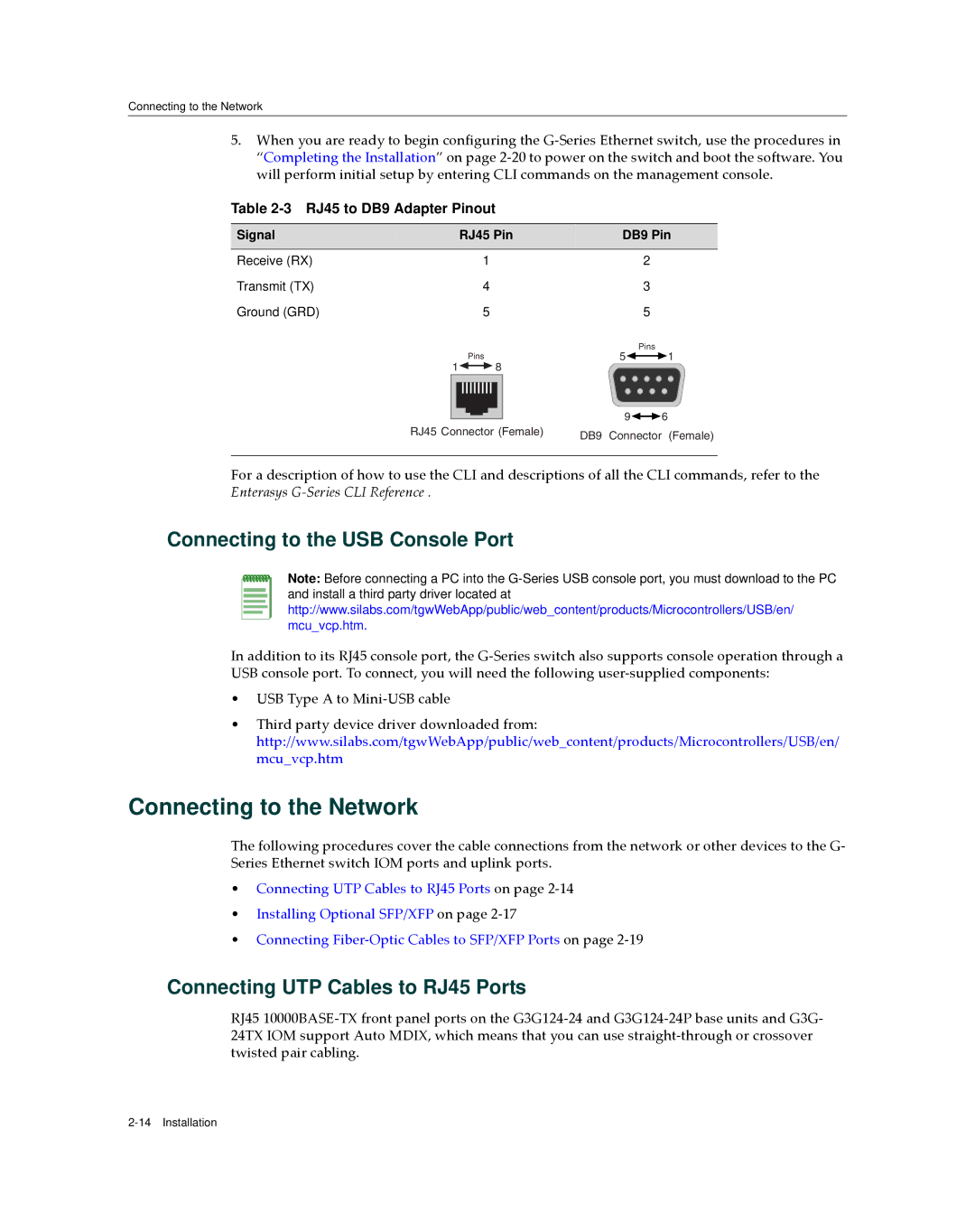
Table 2-3 RJ45 to DB9 Adapter Pinout
Signal | RJ45 Pin |
| DB9 Pin | |
Receive (RX) | 1 |
| 2 |
|
Transmit (TX) | 4 |
| 3 |
|
Ground (GRD) | 5 |
| 5 |
|
|
|
| Pins |
|
| Pins |
| 5 | 1 |
1 | 8 |
|
|
|
|
|
| 9 | 6 |
RJ45 Connector (Female) | DB9 | Connector | (Female) | |
|
| |||
For a description of how to use the CLI and descriptions of all the CLI commands, refer to the Enterasys G‐Series CLI Reference .
Connecting to the USB Console Port
Note: Before connecting a PC into the
In addition to its RJ45 console port, the G‐Series switch also supports console operation through a USB console port. To connect, you will need the following user‐supplied components:
•USB Type A to Mini‐USB cable
•Third party device driver downloaded from: http://www.silabs.com/tgwWebApp/public/web_content/products/Microcontrollers/USB/en/ mcu_vcp.htm
Connecting to the Network
The following procedures cover the cable connections from the network or other devices to the G‐ Series Ethernet switch IOM ports and uplink ports.
•Connecting UTP Cables to RJ45 Ports on page 2‐14
•Installing Optional SFP/XFP on page 2‐17
•Connecting Fiber‐Optic Cables to SFP/XFP Ports on page 2‐19
Connecting UTP Cables to RJ45 Ports
RJ45 10000BASE‐TX front panel ports on the G3G124‐24 and G3G124‐24P base units and G3G‐ 24TX IOM support Auto MDIX, which means that you can use straight‐through or crossover twisted pair cabling.