Installing and Removing an IOM
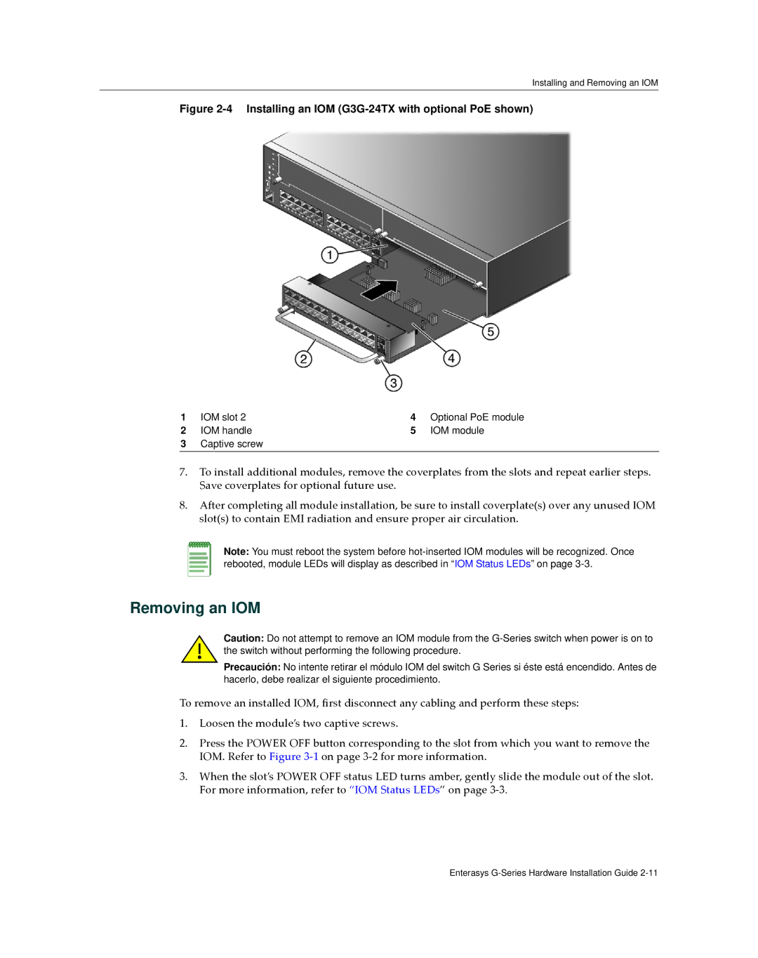
Figure 2-4 Installing an IOM (G3G-24TX with optional PoE shown)
1 | IOM slot 2 | 4 | Optional PoE module |
2 | IOM handle | 5 | IOM module |
3Captive screw
7.To install additional modules, remove the coverplates from the slots and repeat earlier steps. Save coverplates for optional future use.
8.After completing all module installation, be sure to install coverplate(s) over any unused IOM slot(s) to contain EMI radiation and ensure proper air circulation.
Note: You must reboot the system before
Removing an IOM
Caution: Do not attempt to remove an IOM module from the
Precaución: No intente retirar el módulo IOM del switch G Series si éste está encendido. Antes de hacerlo, debe realizar el siguiente procedimiento.
To remove an installed IOM, first disconnect any cabling and perform these steps:
1.Loosen the module’s two captive screws.
2.Press the POWER OFF button corresponding to the slot from which you want to remove the IOM. Refer to Figure 3‐1 on page 3‐2 for more information.
3.When the slot’s POWER OFF status LED turns amber, gently slide the module out of the slot. For more information, refer to “IOM Status LEDs” on page 3‐3.
Enterasys
