Optional Connection
VGA Monitor
Connect the VGA monitor output connector to a VGA monitor. The VGA monitor displays selected live or recorded cameras in any available format.
Call Monitor
Connect the Call monitor output connector to a TV monitor. This monitor displays the full screen images of cameras associated with alarms or images from the installed cameras sequentially.
Alarm In
Connect Alarm In
Alarm Out
Connect Alarm Out 1,2,5,6 to NC type of alarm signals, Alarm Out 3,4,7,8 to NO type.
Microphone/Speaker
Connect the microphone/speaker or other audio devices to the Audio In/Audio out connector.
PTZ Camera
Connect a PTZ camera to the
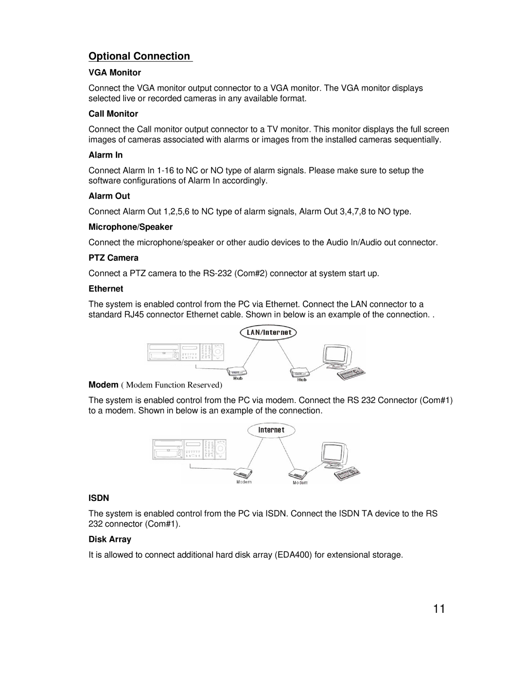
Ethernet
The system is enabled control from the PC via Ethernet. Connect the LAN connector to a standard RJ45 connector Ethernet cable. Shown in below is an example of the connection. .
Modem ( Modem Function Reserved)
The system is enabled control from the PC via modem. Connect the RS 232 Connector (Com#1) to a modem. Shown in below is an example of the connection.
ISDN
The system is enabled control from the PC via ISDN. Connect the ISDN TA device to the RS
232connector (Com#1).
Disk Array
It is allowed to connect additional hard disk array (EDA400) for extensional storage.
11