Installing and Configuring the EVGA nForce 680i SLI Motherboard
Table 2. Front Panel Header Pins
|
|
| Pin | Signal |
| HD_LED |
| 1 | HD_PWR |
|
|
|
| |
|
| 3 | HDA# | |
|
|
| ||
| PWRLED |
| 2 | HDR_BLNK_GRN |
|
|
|
| |
|
| 4 | HDR_BLNK_YEL | |
|
|
| ||
| RESET |
| 5 | GND |
|
|
|
| |
|
| 7 | FP_RESET# | |
|
|
| ||
| PWRSW |
| 6 | SWITCH_ON# |
|
|
|
| |
|
| 8 | GND | |
|
|
| ||
| No Connect |
| 9 |
|
Empty | 10 |
| ||
|
| |||
In/Out
Out
Out
Out
Out
In
In
Description
Hard disk LED
Hard disk active LED
Front panel green light
Front panel yellow light
Ground
Reset switch
Power switch
Ground
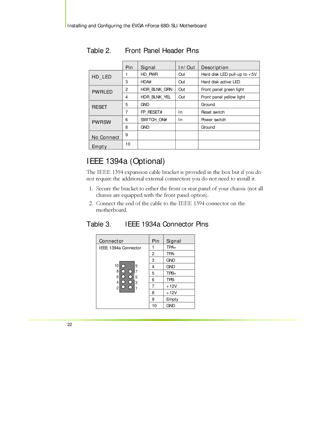
IEEE 1394a (Optional)
The IEEE 1394 expansion cable bracket is provided in the box but if you do not require the additional external connection you do not need to install it.
1.Secure the bracket to either the front or rear panel of your chassis (not all chassis are equipped with the front panel option).
2.Connect the end of the cable to the IEEE 1394 connector on the motherboard.
Table 3. IEEE 1934a Connector Pins
Connector |
|
| Pin |
|
| Signal | |
IEEE 1394a Connector | 1 |
|
| TPA+ | |||
|
|
|
| 2 |
|
| TPA- |
|
|
|
|
|
|
| |
10 |
| 9 |
| 3 |
| GND | |
|
|
|
|
| |||
| 4 |
| GND | ||||
8 |
| 7 |
|
|
|
|
|
| 5 |
|
| TPB+ | |||
6 |
| 5 |
|
|
| ||
|
| 6 |
|
| TPB- | ||
4 |
| 3 |
|
|
| ||
|
|
|
|
|
| ||
| 7 |
|
| +12V | |||
2 |
| 1 |
|
|
| ||
|
|
|
|
|
| ||
| 8 |
|
| +12V | |||
|
|
|
|
|
| ||
|
|
|
|
|
| ||
|
|
|
|
|
|
|
|
|
|
|
| 9 |
|
| Empty |
|
|
|
| 10 |
| GND | |
22