Chapter 2 • Configuration and Installation
Rear Panel Connectors and Indicators
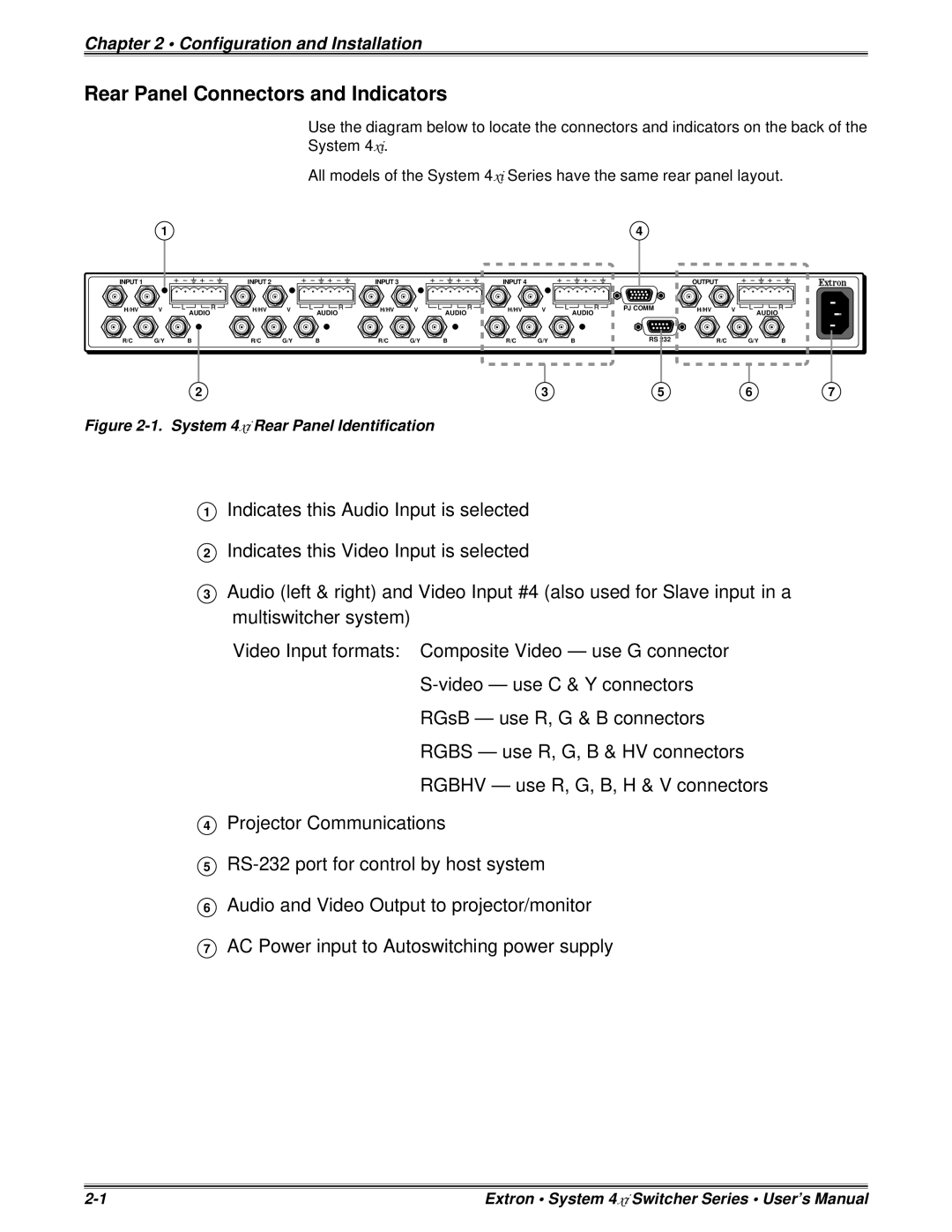
Use the diagram below to locate the connectors and indicators on the back of the
System 4xi.
All models of the System 4xi Series have the same rear panel layout.
1 | 4 |
INPUT 1
INPUT 2
INPUT 3
INPUT 4
OUTPUT
H/HV | V | AUDIO | H/HV | V | AUDIO | H/HV | V | AUDIO | H/HV | V | AUDIO | PJ COMM | H/HV | V | AUDIO |
|
|
|
|
|
|
|
|
|
|
|
R/C G/Y B
R/C | G/Y | B | R/C | G/Y | B | R/C | G/Y | B | RS 232 | R/C | G/Y | B |
2 | 3 | 5 | 6 | 7 |
Figure 2-1. System 4xi Rear Panel Identification
1Indicates this Audio Input is selected
2Indicates this Video Input is selected
3Audio (left & right) and Video Input #4 (also used for Slave input in a multiswitcher system)
Video Input formats: Composite Video — use G connector
RGsB — use R, G & B connectors
RGBS — use R, G, B & HV connectors
RGBHV — use R, G, B, H & V connectors
4Projector Communications
5
6Audio and Video Output to projector/monitor
7AC Power input to Autoswitching power supply
Extron • System 4xi Switcher Series • User’s Manual |
