Chapter 4 • Connecting Multiple Switchers
Programming the System 4xi Looping Configuration
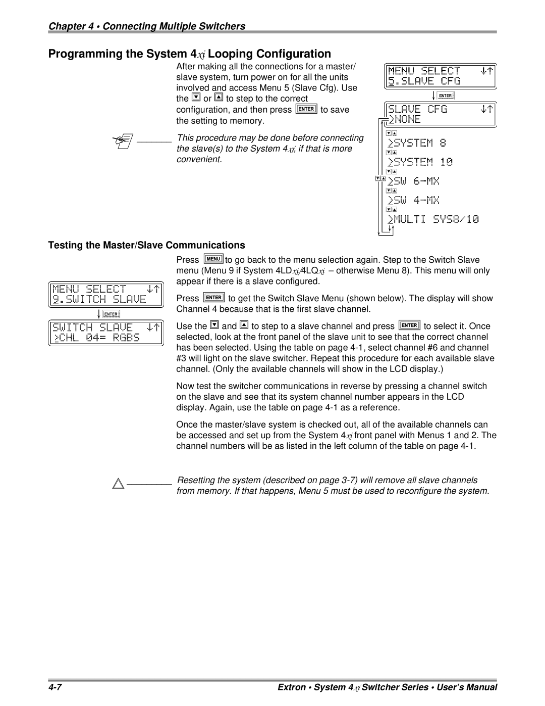
After making all the connections for a master/ slave system, turn power on for all the units involved and access Menu 5 (Slave Cfg). Use the ![]() or
or ![]() to step to the correct
to step to the correct
configuration, and then press ![]() to save the setting to memory.
to save the setting to memory.
_______ This procedure may be done before connecting
the slave(s) to the System 4xi, if that is more convenient.
Testing the Master/Slave Communications
Press ![]() to go back to the menu selection again. Step to the Switch Slave menu (Menu 9 if System 4LDxi/4LQxi – otherwise Menu 8). This menu will only appear if there is a slave configured.
to go back to the menu selection again. Step to the Switch Slave menu (Menu 9 if System 4LDxi/4LQxi – otherwise Menu 8). This menu will only appear if there is a slave configured.
Press ![]() to get the Switch Slave Menu (shown below). The display will show
to get the Switch Slave Menu (shown below). The display will show
Channel 4 because that is the first slave channel.
Use the ![]() and
and ![]() to step to a slave channel and press
to step to a slave channel and press ![]() to select it. Once selected, look at the front panel of the slave unit to see that the correct channel has been selected. Using the table on page
to select it. Once selected, look at the front panel of the slave unit to see that the correct channel has been selected. Using the table on page
Now test the switcher communications in reverse by pressing a channel switch on the slave and see that its system channel number appears in the LCD display. Again, use the table on page
Once the master/slave system is checked out, all of the available channels can be accessed and set up from the System 4xi front panel with Menus 1 and 2. The channel numbers will be as listed in the left column of the table on page
_________ Resetting the system (described on page
from memory. If that happens, Menu 5 must be used to reconfigure the system.
Extron • System 4xi Switcher Series • User’s Manual |
