Chapter 3 • Using the System 4xi Front Panel
0. Menu Select/Exit Menu
The Menu button ( ![]()
![]()
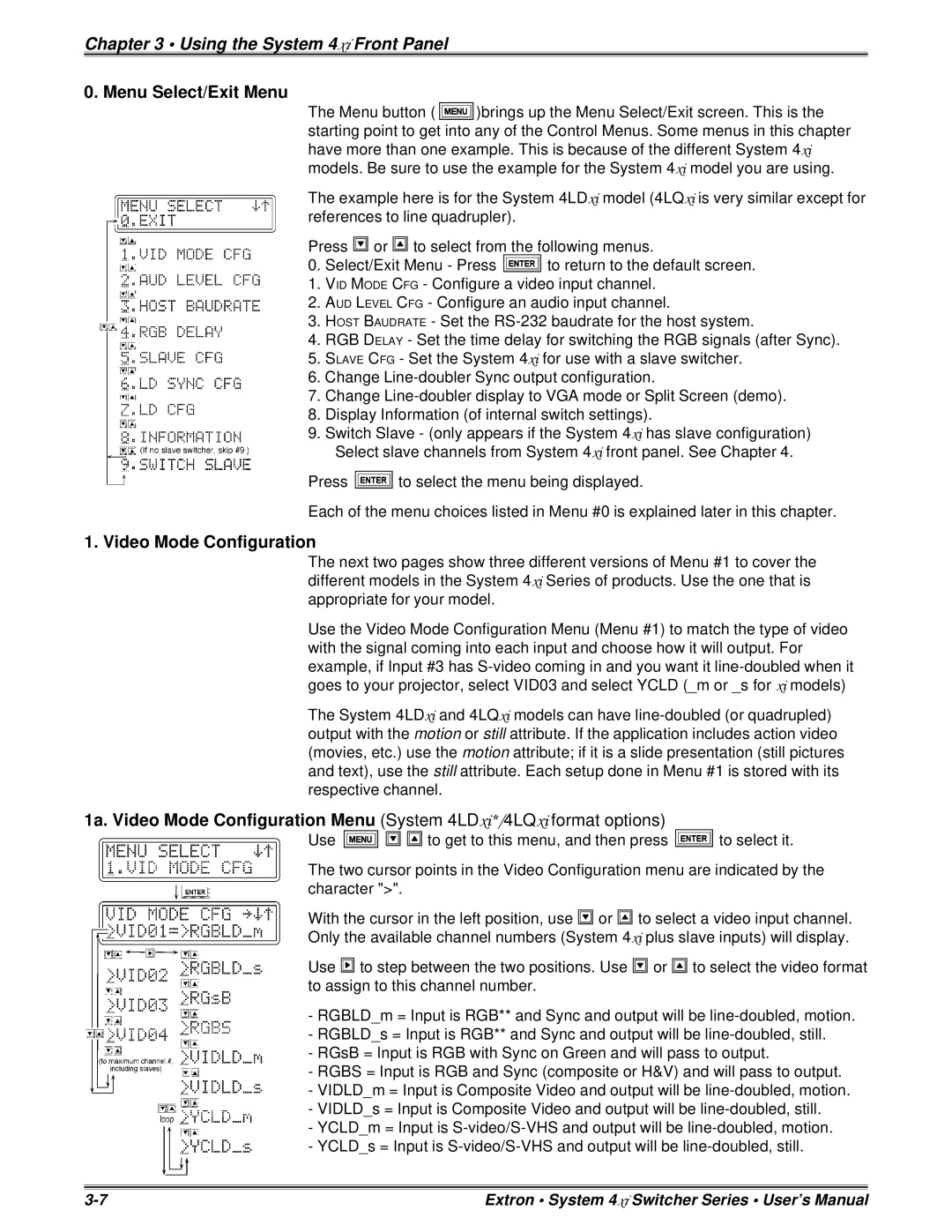
![]() )brings up the Menu Select/Exit screen. This is the starting point to get into any of the Control Menus. Some menus in this chapter have more than one example. This is because of the different System 4xi models. Be sure to use the example for the System 4xi model you are using.
)brings up the Menu Select/Exit screen. This is the starting point to get into any of the Control Menus. Some menus in this chapter have more than one example. This is because of the different System 4xi models. Be sure to use the example for the System 4xi model you are using.
The example here is for the System 4LDxi model (4LQxi is very similar except for references to line quadrupler).
Press ![]() or
or ![]() to select from the following menus.
to select from the following menus.
0.Select/Exit Menu - Press ![]() to return to the default screen.
to return to the default screen.
1.VID MODE CFG - Configure a video input channel.
2.AUD LEVEL CFG - Configure an audio input channel.
3.HOST BAUDRATE - Set the
4.RGB DELAY - Set the time delay for switching the RGB signals (after Sync).
5.SLAVE CFG - Set the System 4xi for use with a slave switcher.
6.Change
7.Change
8.Display Information (of internal switch settings).
9.Switch Slave - (only appears if the System 4xi has slave configuration) Select slave channels from System 4xi front panel. See Chapter 4.
Press ![]() to select the menu being displayed.
to select the menu being displayed.
Each of the menu choices listed in Menu #0 is explained later in this chapter.
1. Video Mode Configuration
The next two pages show three different versions of Menu #1 to cover the different models in the System 4xi Series of products. Use the one that is appropriate for your model.
Use the Video Mode Configuration Menu (Menu #1) to match the type of video with the signal coming into each input and choose how it will output. For example, if Input #3 has
The System 4LDxi and 4LQxi models can have
1a. Video Mode Configuration Menu (System 4LDxi*/4LQxi format options)
Use ![]()
![]()
![]() to get to this menu, and then press
to get to this menu, and then press ![]() to select it.
to select it.
The two cursor points in the Video Configuration menu are indicated by the character ">".
With the cursor in the left position, use ![]() or
or ![]() to select a video input channel.
to select a video input channel.
Only the available channel numbers (System 4xi plus slave inputs) will display.
Use ![]() to step between the two positions. Use
to step between the two positions. Use ![]() or
or ![]() to select the video format to assign to this channel number.
to select the video format to assign to this channel number.
-RGBLD_m = Input is RGB** and Sync and output will be
-RGBLD_s = Input is RGB** and Sync and output will be
-RGsB = Input is RGB with Sync on Green and will pass to output.
-RGBS = Input is RGB and Sync (composite or H&V) and will pass to output.
-VIDLD_m = Input is Composite Video and output will be
-VIDLD_s = Input is Composite Video and output will be
-YCLD_m = Input is
-YCLD_s = Input is
Extron • System 4xi Switcher Series • User’s Manual |
