Chapter 4 • Connecting Multiple Switchers
Controlling Master/Slave Switchers
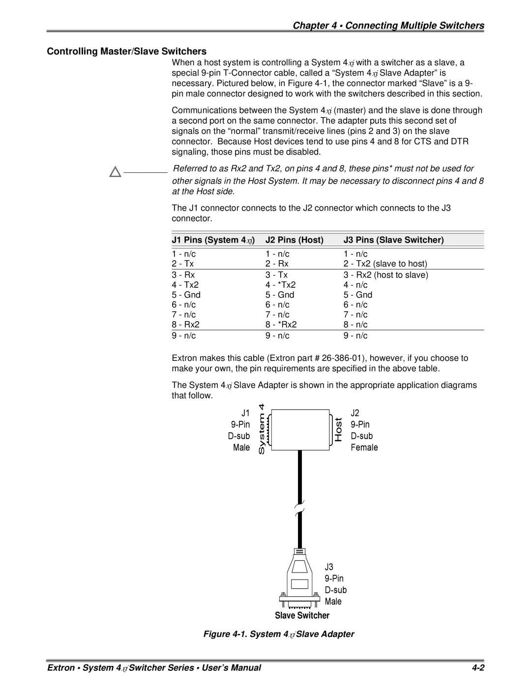
When a host system is controlling a System 4xi with a switcher as a slave, a special
Communications between the System 4xi (master) and the slave is done through a second port on the same connector. The adapter puts this second set of signals on the “normal” transmit/receive lines (pins 2 and 3) on the slave connector. Because Host devices tend to use pins 4 and 8 for CTS and DTR signaling, those pins must be disabled.
![]() _________ Referred to as Rx2 and Tx2, on pins 4 and 8, these pins* must not be used for
_________ Referred to as Rx2 and Tx2, on pins 4 and 8, these pins* must not be used for
other signals in the Host System. It may be necessary to disconnect pins 4 and 8 at the Host side.
The J1 connector connects to the J2 connector which connects to the J3 connector.
J1 Pins (System 4xi) | J2 Pins (Host) | J3 Pins (Slave Switcher) | |||
|
|
|
|
|
|
|
|
|
|
|
|
1 | - n/c | 1 | - n/c | 1 | - n/c |
2 | - Tx | 2 | - Rx | 2 | - Tx2 (slave to host) |
3 | - Rx | 3 | - Tx | 3 | - Rx2 (host to slave) |
4 | - Tx2 | 4 | - *Tx2 | 4 | - n/c |
5 | - Gnd | 5 | - Gnd | 5 | - Gnd |
6 | - n/c | 6 | - n/c | 6 | - n/c |
7 | - n/c | 7 | - n/c | 7 | - n/c |
8 | - Rx2 | 8 | - *Rx2 | 8 | - n/c |
9 | - n/c | 9 | - n/c | 9 | - n/c |
Extron makes this cable (Extron part #
The System 4xi Slave Adapter is shown in the appropriate application diagrams that follow.
Slave Switcher
Figure 4-1. System 4xi Slave Adapter
Extron • System 4xi Switcher Series • User’s Manual |
