System 4xi Switcher Series
Getting Started..........
ττStep 1 υυ
If the System 4xi is already configured for your model of projector, go to Step 4. If it is not set up correctly, it will be necessary to change switch settings on the System 4xi ’s Main Controller Board. Continue with Step 2 below to verify the correct configuration.
ττStep 2 υυ
Apply power to the System 4xi. Use the front panel to display the Information Menu (Menu 8). If the configuration is correct, go to Step 4. If it is not correct, continue with Step 3.
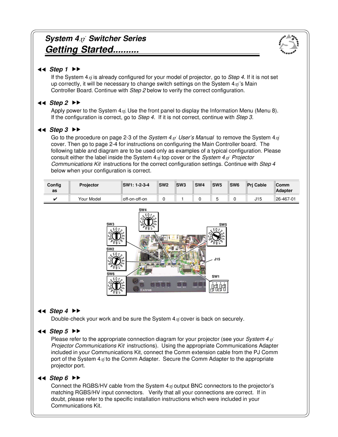
ττStep 3 υυ
Go to the procedure on page
Config | Projector | SW1: | SW2 | SW3 | SW4 | SW5 | SW6 | Prj Cable | Comm |
as |
|
|
|
|
|
|
|
| Adapter |
|
|
|
|
|
|
|
|
|
|
|
|
|
|
|
|
|
|
|
|
✔ | Your Model | 0 | 1 | 0 | 5 | 0 | J15 | ||
|
|
|
|
|
|
|
|
|
|
SW3 |
SW2 |
SW6 |
SW4 |
SW5 |
J15
SW1
4 | 3 | 2 | 1 |
ττStep 4 υυ
ττStep 5 υυ
Please refer to the appropriate connection diagram for your projector (see your System 4xi Projector Communications Kit instructions). Using the appropriate Communications Adapter included in your Communications Kit, connect the Comm extension cable from the PJ Comm port of the System 4xi to the Comm Adapter. Secure the Comm Adapter to the appropriate projector port.
ττStep 6 υυ
Connect the RGBS/HV cable from the System 4xi output BNC connectors to the projector’s matching RGBS/HV input connectors. Verify that all your connections are correct. If in doubt, please refer to the specific installation instructions which were included in your Communications Kit.