Chapter 2 • Configuration and Installation
2.If your unit is not set up correctly, remove the System 4xi cover (page
3.Set the switches as indicated by the label or the instructions included with the projector communications kit and verify that the Projector cable is on the correct connector (J9/J15).
_______ Extron continues to support new projectors. If you have questions about using
the System 4xi with a device for which you cannot find configuration settings, please consult with your Extron representative.
4.Refer to the appropriate cabling procedure included with the projector communications kit to continue the installation.
Cabling a System 4xi in a Rack
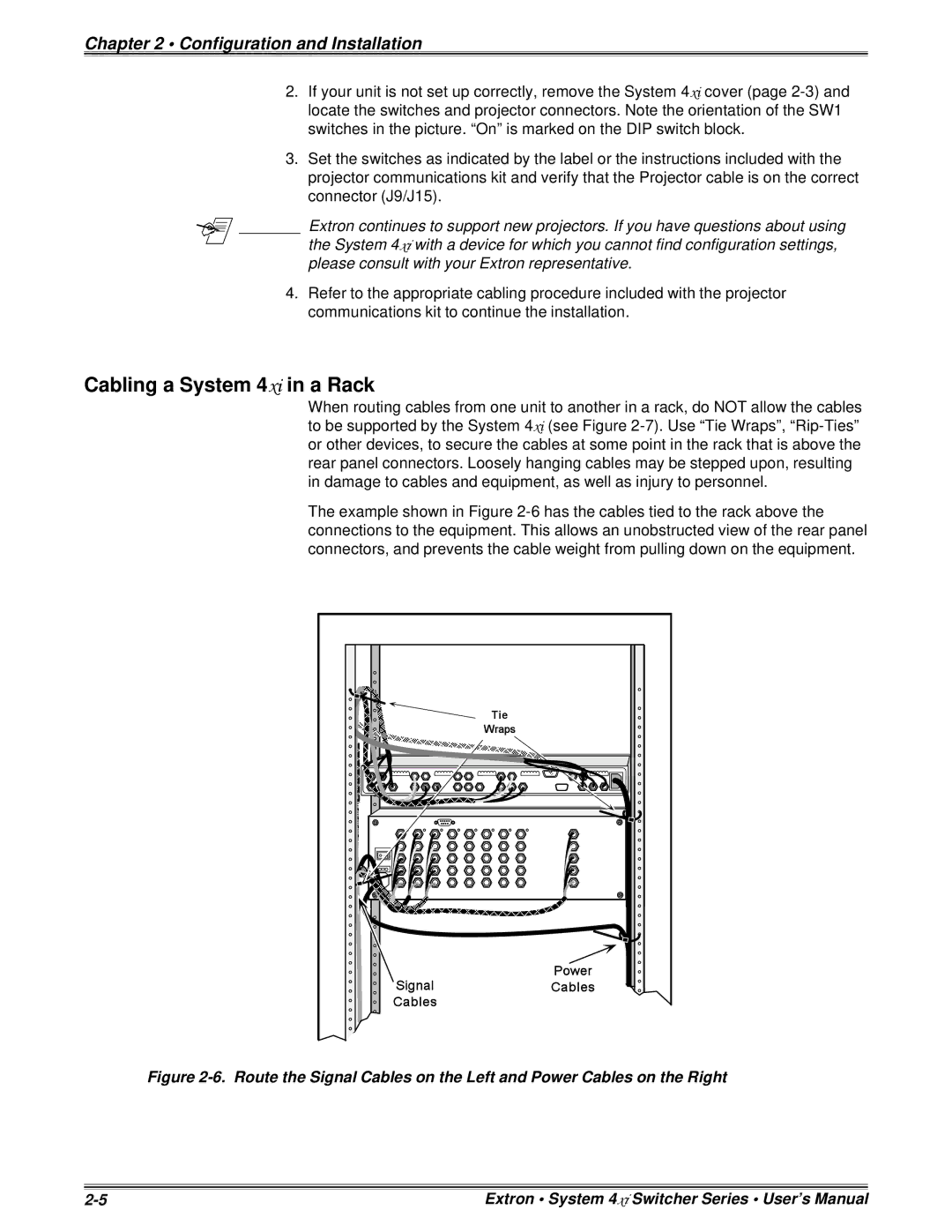
When routing cables from one unit to another in a rack, do NOT allow the cables to be supported by the System 4xi (see Figure
The example shown in Figure
Figure 2-6. Route the Signal Cables on the Left and Power Cables on the Right
Extron • System 4xi Switcher Series • User’s Manual |