Power connection
1AC power connector — Plug a standard IEC power cord into this connector to connect the switcher to a 100 to 240VAC, 50 Hz or 60 Hz power source.
Video input and output connections (video models only)
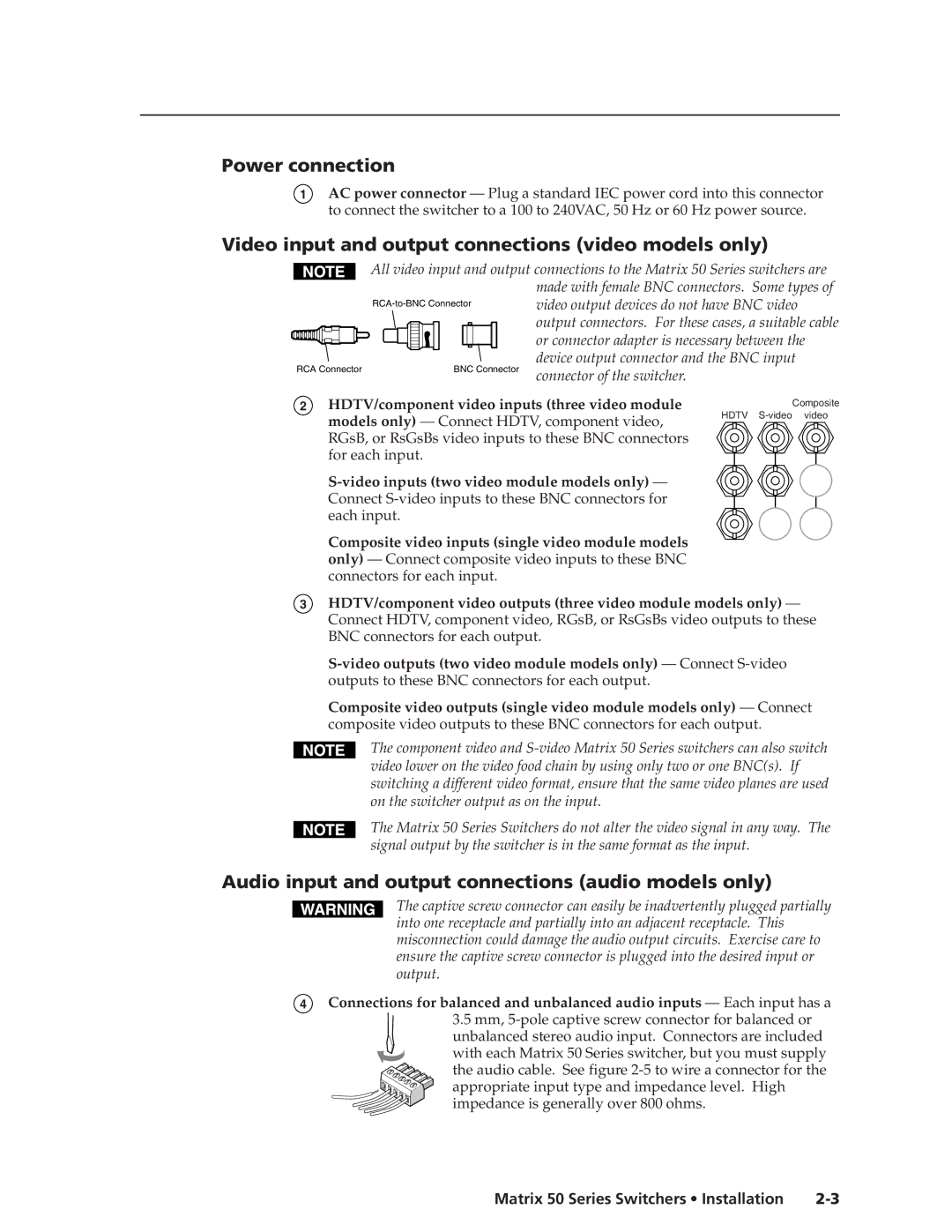
All video input and output connections to the Matrix 50 Series switchers are made with female BNC connectors. Some types of video output devices do not have BNC video
RCA Connector
output connectors. For these cases, a suitable cable or connector adapter is necessary between the device output connector and the BNC input connector of the switcher.
2
HDTV/component video inputs (three video module
models only) — Connect HDTV, component video, RGsB, or RsGsBs video inputs to these BNC connectors for each input.
Composite video inputs (single video module models only) — Connect composite video inputs to these BNC connectors for each input.
Composite
HDTV S-video video
3
HDTV/component video outputs (three video module models only) — Connect HDTV, component video, RGsB, or RsGsBs video outputs to these BNC connectors for each output.
Composite video outputs (single video module models only) — Connect composite video outputs to these BNC connectors for each output.
The component video and
The Matrix 50 Series Switchers do not alter the video signal in any way. The signal output by the switcher is in the same format as the input.
Audio input and output connections (audio models only)
The captive screw connector can easily be inadvertently plugged partially into one receptacle and partially into an adjacent receptacle. This misconnection could damage the audio output circuits. Exercise care to ensure the captive screw connector is plugged into the desired input or output.
4Connections for balanced and unbalanced audio inputs — Each input has a
3.5mm, 5-pole captive screw connector for balanced or
unbalanced stereo audio input. Connectors are included with each Matrix 50 Series switcher, but you must supply the audio cable. See figure
Matrix 50 Series Switchers • Installation |