Programmer’ser’sGuide,Guidecont’d
The switcher’s rear panel
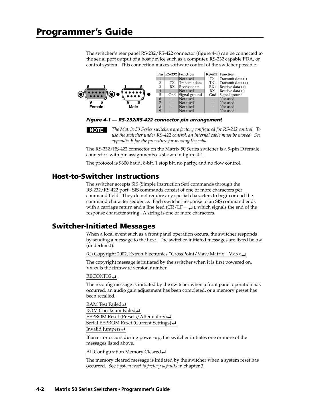
5 | 1 | 1 | 5 |
9 | 6 | 6 | 9 |
Female | Male | ||
Pin |
| Function |
| Function |
1 | — | Not used | TX- | Transmit data |
2 | TX | Transmit data | TX+ | Transmit data (+) |
3 | RX | Receive data | RX+ | Receive data (+) |
4 | — | Not used | RX- | Receive data |
5 | Gnd | Signal ground | Gnd | Signal ground |
6 | — | Not used | — | Not used |
7 | — | Not used | — | Not used |
8 | — | Not used | — | Not used |
9 | — | Not used | — | Not used |
Figure 4-1 — RS-232/RS-422 connector pin arrangement
The Matrix 50 Series switchers are factory configured for
The
The protocol is 9600 baud,
Host-to-Switcher Instructions
The switcher accepts SIS (Simple Instruction Set) commands through the ![]() ), which signals the end of the response character string. A string is one or more characters.
), which signals the end of the response character string. A string is one or more characters.
Switcher-Initiated Messages
When a local event such as a front panel operation occurs, the switcher responds by sending a message to the host. The
(C) Copyright 2002, Extron Electronics “CrossPoint/Mav/Matrix”, Vx.xx![]()
The copyright message is initiated by the switcher when it is first powered on. Vx.xx is the firmware version number.
RECONFIG
The reconfig message is initiated by the switcher when a front panel operation has occurred, an audio gain adjustment has been completed, or a memory preset has been recalled.
RAM Test Failed![]()
ROM Checksum Failed![]()
EEPROM Reset (Presets/Attenuators)![]()
Serial EEPROM Reset (Current Settings)![]()
Invalid Jumpers![]()
If an error occurs during
All Configuration Memory Cleared![]()
The memory cleared message is initiated by the switcher when a system reset has occurred. See System reset to factory defaults in chapter 3.