Matrix 50 Series Switchers • Reference Information
9.
Reconnect the input and output cables.
If you choose to check for proper operation before putting the cover back on, ensure that tools and hands are outside the switcher, and then connect the power cord to the unit and to an AC source. The switcher should power up normally. Unplug the AC power cord, and reinstall the switcher.
7. Attach the power cord to the switcher and to the AC power source. Ensure the switcher is working properly.
8. If the switcher was removed from a rack, remove its power cord, reattach the switcher to the rack, and reconnect the power cord.
6. Reinstall the switcher’s cover. See Closing the switcher on page B-3.
5. Plug the cable in to the desired receptacle by aligning the holes in the connector with the pins in the RS-232 or RS-422 receptacle, and pressing evenly until the receptacle tabs lock into place.
Connector
Ribbon cable
4.
Remove the RS-232/RS-422 ribbon cable by pressing the two RS-232/RS-422 receptacle tabs outward as shown at the left, and pull up evenly
on the cable connector to remove it from the current receptacle.
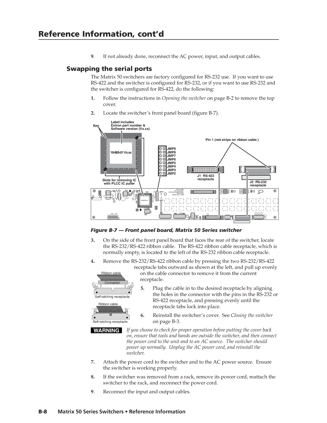
Figure B-7 — Front panel board, Matrix 50 Series switcher
3. On the side of the front panel board that faces the rear of the switcher, locate the RS-232/RS-422 ribbon cable. The RS-422 ribbon cable receptacle, which is normally empty, is located to the left of the RS-232 ribbon cable receptacle.
Reference Information, cont’d
9. | If not already done, reconnect the AC power, input, and output cables. |
Swapping the serial ports
The Matrix 50 switchers are factory configured for
1.Follow the instructions in Opening the switcher on page
2.Locate the switcher’s front panel board (figure
Label includes
Key Extron part number &
Software version (Vx.xx)
| Pin 1 (red stripe on ribbon cable ) | |
| JMP9 | |
JMP8 | ||
| JMP7 | |
| JMP6 | |
| JMP5 | |
| JMP4 | |
| JMP3 | |
| JMP2 | |
| J1 | |
Slots for removing IC | receptacle | |
J2 | ||
with PLCC IC puller | ||
receptacle | ||
| ||
U7 |
| |
|