ReferenceInformation,co t’d
Hardware Procedures
This appendix contains procedures for performing hardware maintenance operations such as installing a Matrix 50 Option Kit, swapping the
Opening the switcher
Before you can perform any of the hardware upgrade procedures, you must open the switcher. To open the switcher, do the following:
1.Disconnect the power cord from the switcher.
2.If the switcher is rack mounted, remove the switcher from the rack and place it on a clean workspace.
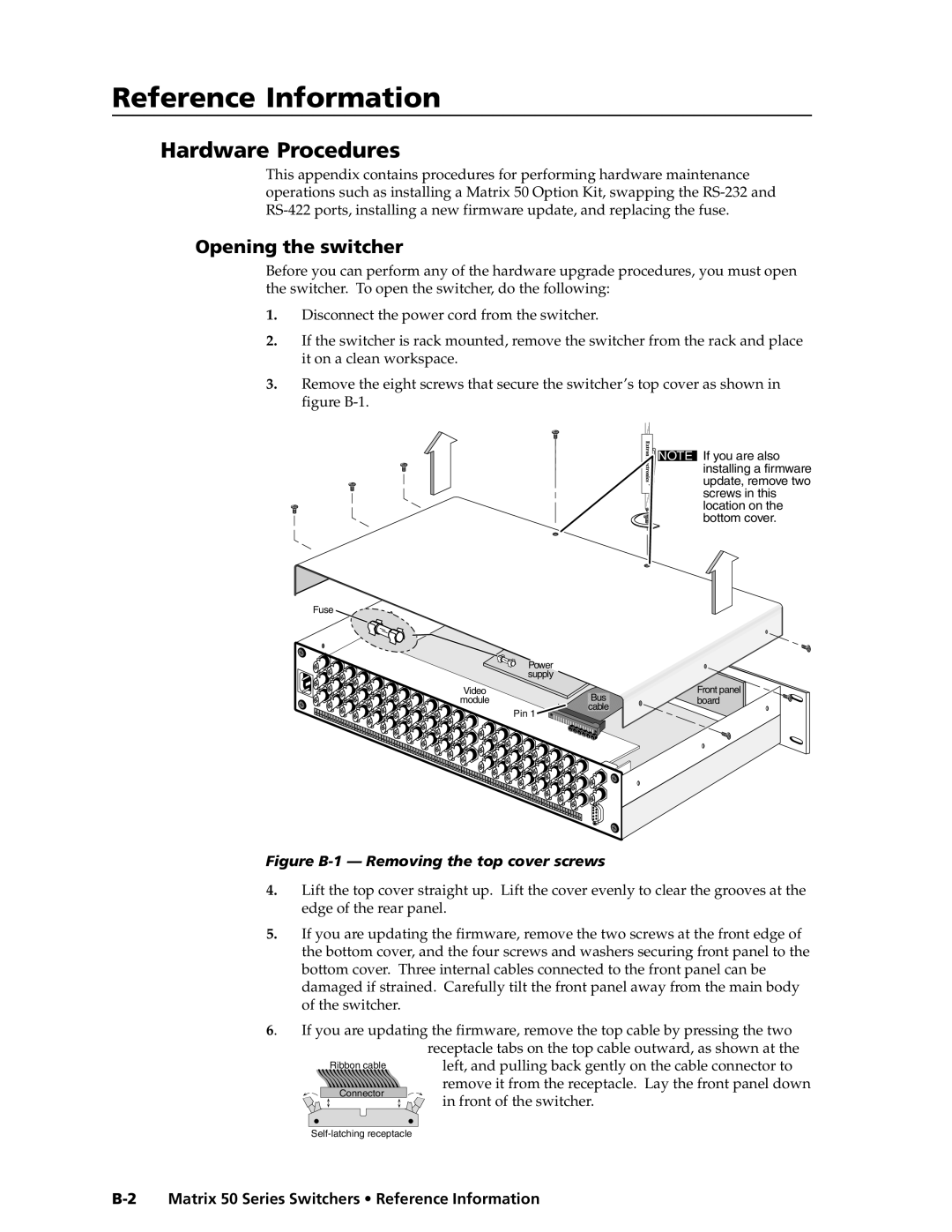
3.Remove the eight screws that secure the switcher’s top cover as shown in figure
Fuse
| Power |
| supply |
Video | Bus |
module | |
| cable |
| Pin 1 |
NOTE If you are also installing a firmware update, remove two screws in this location on the bottom cover.
Front panel board
Figure B-1 — Removing the top cover screws
4.Lift the top cover straight up. Lift the cover evenly to clear the grooves at the edge of the rear panel.
5.If you are updating the firmware, remove the two screws at the front edge of the bottom cover, and the four screws and washers securing front panel to the bottom cover. Three internal cables connected to the front panel can be damaged if strained. Carefully tilt the front panel away from the main body of the switcher.
6. If you are updating the firmware, remove the top cable by pressing the two
| receptacle tabs on the top cable outward, as shown at the | |
Ribbon cable | left, and pulling back gently on the cable connector to | |
Connector | remove it from the receptacle. Lay the front panel down | |
in front of the switcher. | ||
| ||
|