Extron electronic 50 Installation, cont’d, RS-232/422 connection, 6 - Phono audio connectors

Models: 50

1 74
Download 74 pages 18.11 Kb
Page 18
Image 18
Installation, cont’d

Installation, cont’d

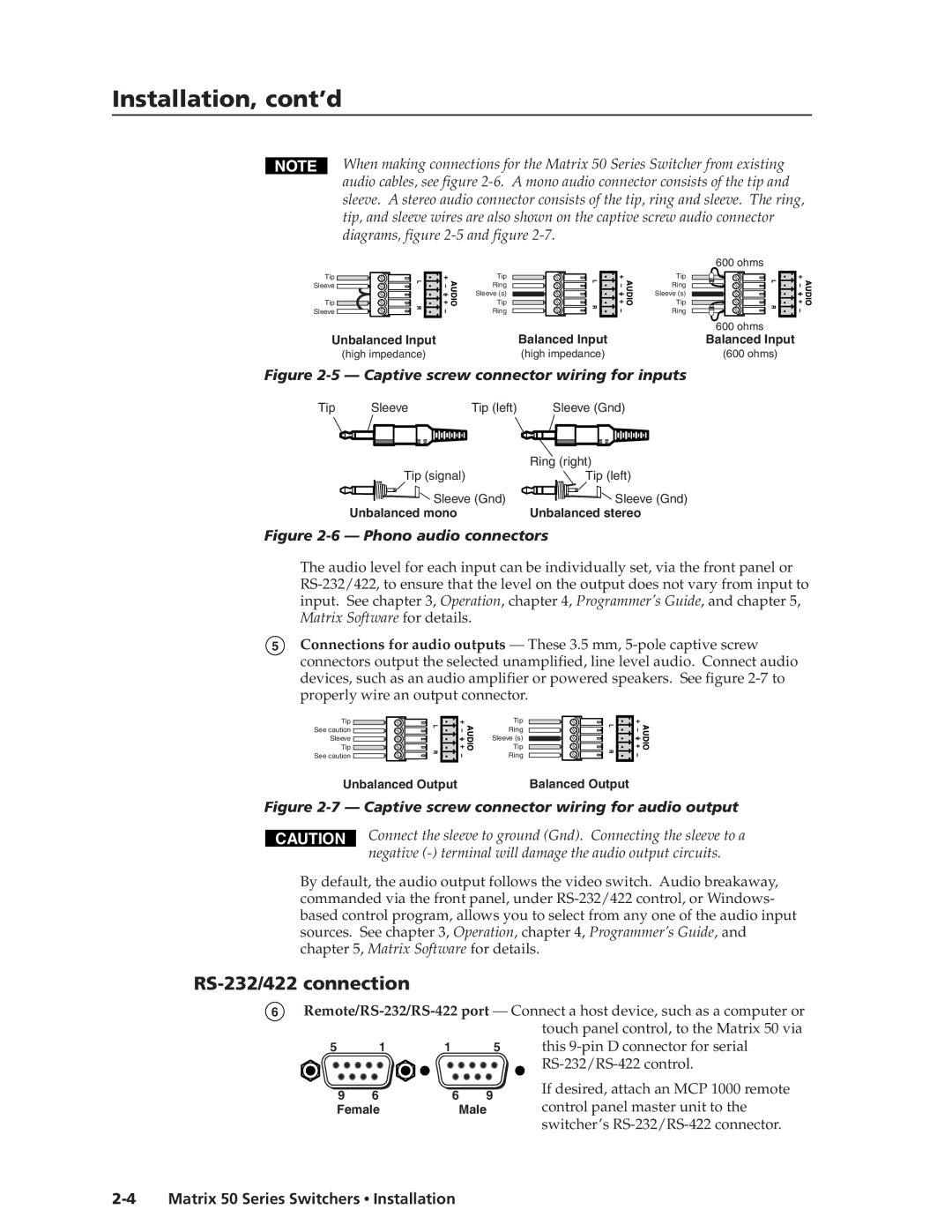
When making connections for the Matrix 50 Series Switcher from existing audio cables, see figure 2-6. A mono audio connector consists of the tip and sleeve. A stereo audio connector consists of the tip, ring and sleeve. The ring, tip, and sleeve wires are also shown on the captive screw audio connector diagrams, figure 2-5 and figure 2-7.

Tip

Sleeve

Tip

Sleeve

Unbalanced Input

(high impedance)

Tip

Ring

Sleeve (s)

Tip

Ring

Balanced Input

(high impedance)

600 ohms

Tip

Ring

Sleeve (s)

Tip

Ring

600ohms

Balanced Input

(600 ohms)

Figure 2-5 — Captive screw connector wiring for inputs

Tip

Sleeve

Tip (left)

Sleeve (Gnd)


Ring (right)


Tip (signal)


Tip (left)


Sleeve (Gnd)

Sleeve (Gnd)


Unbalanced mono


Unbalanced stereo

Figure 2-6 — Phono audio connectors

The audio level for each input can be individually set, via the front panel or RS-232/422, to ensure that the level on the output does not vary from input to input. See chapter 3, Operation, chapter 4, Programmer’s Guide, and chapter 5, Matrix Software for details.

5Connections for audio outputs — These 3.5 mm, 5-pole captive screw connectors output the selected unamplified, line level audio. Connect audio devices, such as an audio amplifier or powered speakers. See figure 2-7 to properly wire an output connector.

Tip Figure 2-5 — Captive screw connector wiring for inputs See caution Figure 2-6 — Phono audio connectors Sleeve Figure 2-7 — Captive screw connector wiring for audio output Tip RS-232/422 connection

See caution 2-4 Matrix 50 Series Switchers • Installation

Tip

Ring

Sleeve (s)

Tip

Ring

Unbalanced Output

Balanced Output

Figure 2-7 — Captive screw connector wiring for audio output

CAUTION

Connect the sleeve to ground (Gnd). Connecting the sleeve to a negative (-) terminal will damage the audio output circuits.

By default, the audio output follows the video switch. Audio breakaway, commanded via the front panel, under RS-232/422 control, or Windows- based control program, allows you to select from any one of the audio input sources. See chapter 3, Operation, chapter 4, Programmer’s Guide, and chapter 5, Matrix Software for details.

RS-232/422 connection

6Remote/RS-232/RS-422 port — Connect a host device, such as a computer or touch panel control, to the Matrix 50 via

5

1

1

5

this 9-pin D connector for serial


RS-232/RS-422 control.

9

6

6

9

If desired, attach an MCP 1000 remote

control panel master unit to the

Female

Male

switcher’s RS-232/RS-422 connector.

2-4 Matrix 50 Series Switchers Installation

Page 18
Image 18
Extron electronic 50 manual Installation, cont’d, RS-232/422 connection, 5 - Captive screw connector wiring for inputs