Operation, cont’d
CPress and release the input 5 button. The input 5 LED lights.
DPress and release the output 3, output 4, and output 8 buttons. The output 3, output 4, and output 8 LEDs blink to indicate a tentative tie.
The entire set of ties can be canceled at this point by pressing and releasing the Esc button. The Esc LED flashes once.
EPress and release the Enter button. The input and output LEDs turn off. The current configuration is now defined as video and audio input 5 tied to video and audio output 3, output 4, and output 8.
Example 2: Adding a tie to a set of video and audio ties
See figure
|
|
|
| 5 |
|
| LED key: |
| = off, | = on, B = blinking, | Press | |||
|
|
|
|
|
|
|
| |||||||
|
|
| Press |
|
|
|
|
| F | = flash once |
|
| B | |
|
|
|
|
|
|
|
|
|
|
| ||||
|
|
|
|
|
| C |
|
|
|
|
|
|
| |
|
|
|
|
|
|
|
|
|
|
|
|
| VIDEO | |
|
|
|
|
| INPUTS |
|
|
|
|
|
|
| ||
|
|
|
|
|
|
|
|
|
|
|
|
| ||
1 | 2 | 3 | 4 | 5 | 6 | 7 | 8 | 9 | 10 | 11 | 12 |
|
|
|
|
|
|
|
|
|
|
|
|
|
|
| CONTROL |
| I/O |
1 | 2 | 3 | 4 | 5 | 6 | 7 | 8 |
|
|
|
| ENTER PRESET VIEW | ESC | VIDEO AUDIO |
|
|
| OUTPUTS |
|
|
|
|
|
|
|
|
|
| |
|
|
|
| C |
|
|
| C |
|
| Press | Press F |
| |
B |
| 3 | 4 |
|
|
| 8 |
|
|
|
| |||
|
|
|
|
|
|
|
|
|
|
| ||||
Press |
|
|
|
|
|
|
|
|
|
|
| E |
| A |
|
|
|
|
|
|
|
|
|
|
|
|
| ||
|
| D |
|
|
|
|
|
|
|
| ENTER | ESC |
| |
|
|
|
|
|
|
|
|
|
|
|
| |||
1 |
|
|
|
|
|
|
|
|
|
|
|
|
|
|
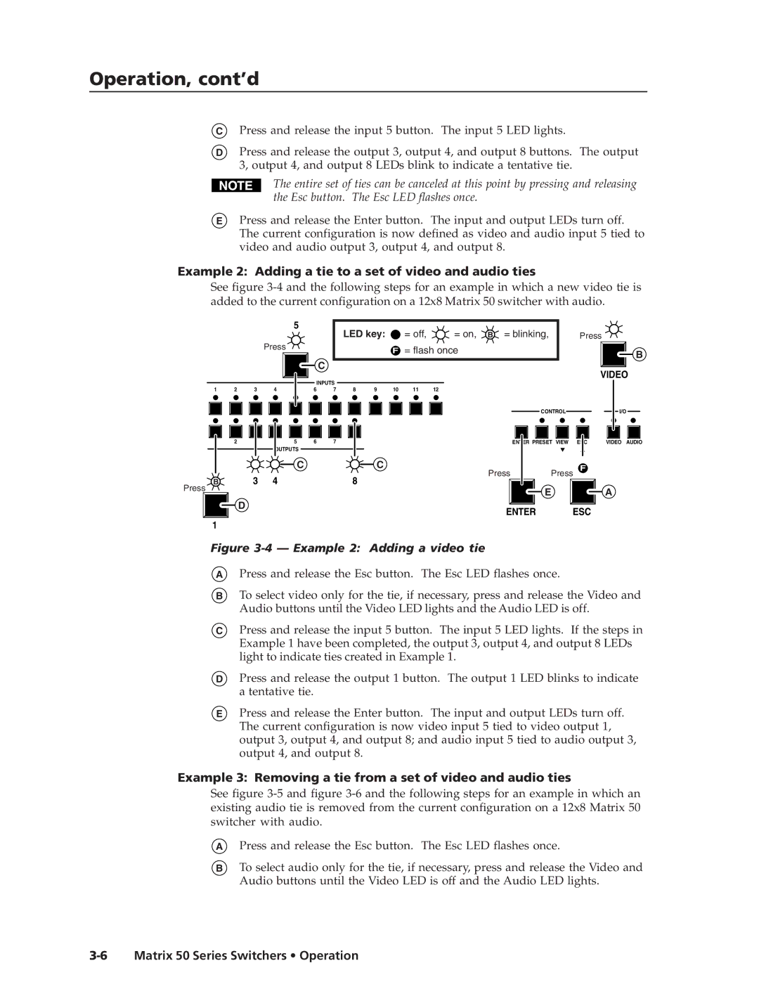
Figure 3-4 — Example 2: Adding a video tie
APress and release the Esc button. The Esc LED flashes once.
BTo select video only for the tie, if necessary, press and release the Video and Audio buttons until the Video LED lights and the Audio LED is off.
CPress and release the input 5 button. The input 5 LED lights. If the steps in Example 1 have been completed, the output 3, output 4, and output 8 LEDs light to indicate ties created in Example 1.
DPress and release the output 1 button. The output 1 LED blinks to indicate a tentative tie.
EPress and release the Enter button. The input and output LEDs turn off. The current configuration is now video input 5 tied to video output 1, output 3, output 4, and output 8; and audio input 5 tied to audio output 3, output 4, and output 8.
Example 3: Removing a tie from a set of video and audio ties
See figure
APress and release the Esc button. The Esc LED flashes once.
BTo select audio only for the tie, if necessary, press and release the Video and Audio buttons until the Video LED is off and the Audio LED lights.