DMP 44 LC specifications
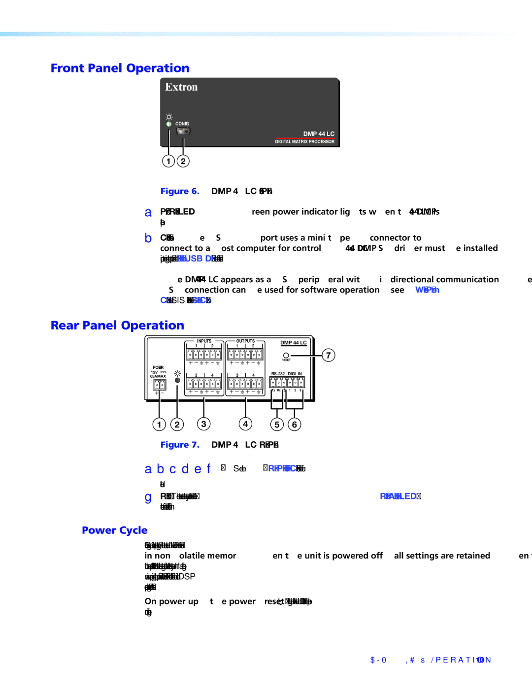
The Extron DMP 44 LC is a powerful digital audio processor designed to cater to a wide range of audio distribution and mixing applications. It combines advanced audio processing capabilities with intuitive controls, making it an ideal solution for classrooms, conference rooms, and other professional audio environments. The DMP 44 LC features four inputs and four outputs, which provide incredible flexibility for any audio setup.One of the standout features of the DMP 44 LC is its comprehensive DSP capabilities. The device incorporates Extron's renowned DSP technology, which offers extensive signal processing functionality including automatic mixing, gain sharing, EQ, delay, and filtering. These tools allow users to optimize audio performance, ensuring that sound quality is consistent and clear across all speakers and microphones.
In terms of connectivity, the DMP 44 LC offers a versatile array of input and output options. It includes balanced, low-impedance microphone and line level inputs, ensuring compatibility with a wide variety of audio sources. Outputs are also balanced, allowing for seamless integration with professional audio systems. The unit’s input and output configuration can be easily customized, accommodating different audio formats and setups.
The DMP 44 LC utilizes Extron’s patented ProDSP technology, which delivers precise signal processing capabilities without sacrificing audio quality. This technology supports high-resolution audio processing, enabling users to achieve the best sound reproduction possible. Moreover, the device allows for remote control and monitoring via an intuitive web-based interface, making it easy to manage audio settings from any location.
Another key characteristic of the DMP 44 LC is its robust design tailored for professional use. The compact form factor can be easily integrated into various environments, whether mounted in a rack or placed on a shelf. Additionally, its enhanced thermal management and sturdy construction ensure reliability and durability in demanding applications.
The DMP 44 LC embodies the latest advancements in audio technology, making it a reliable choice for professionals seeking high-quality sound management. With its extensive features, the digital audio processor allows for seamless audio mixing and processing, ensuring optimal performance in any audiovisual setup.

