Configuration and Operation
1 2 |
|
| ON |
|
| ||
|
| ||
|
| ||
|
|
| |
3 |
|
|
|
|
|
| |
4 |
|
|
|
5 6 |
|
| |
|
| ||
|
| ||
|
| ||
7 |
|
|
|
|
|
| |
|
|
| |
8 |
|
| |
|
|
|
|
UART1_ON
UART4_ON IrDA_ON NEXUS_ON, (Set to OFF) JTAG_CTRL, (Set to OFF)
TONE_OUT
PEN_CS_B
PEN_IRQ_B
S1
Figure 2-1. Switch S1
2.2.2Mode/User Switch (S2)
S2 is a DIP switch that consists of eight slide switches.
Table
. | Table |
|
| |||
|
|
| ||||
|
|
|
|
|
|
|
| Boot Mode, Device | BOOT3 | BOOT2 |
| BOOT1 | BOOT0 |
|
|
| ||||
|
|
| ||||
|
|
|
|
|
|
|
| Internal bootstrap ROM (USB/UART) | ON | ON |
| ON | ON/OFF |
|
|
|
|
|
|
|
| NAND, | ON | ON |
| OFF | ON |
|
|
|
|
|
|
|
| NAND, | ON | ON |
| OFF | OFF |
|
|
|
|
|
|
|
| NAND, | ON | OFF |
| ON | ON |
|
|
|
|
|
|
|
| CS0, | ON | OFF |
| ON | OFF |
|
|
|
|
|
|
|
| CS0, | ON | OFF |
| OFF | ON |
|
|
|
|
|
|
|
| NAND | ON | OFF |
| OFF | OFF |
|
|
|
|
|
|
|
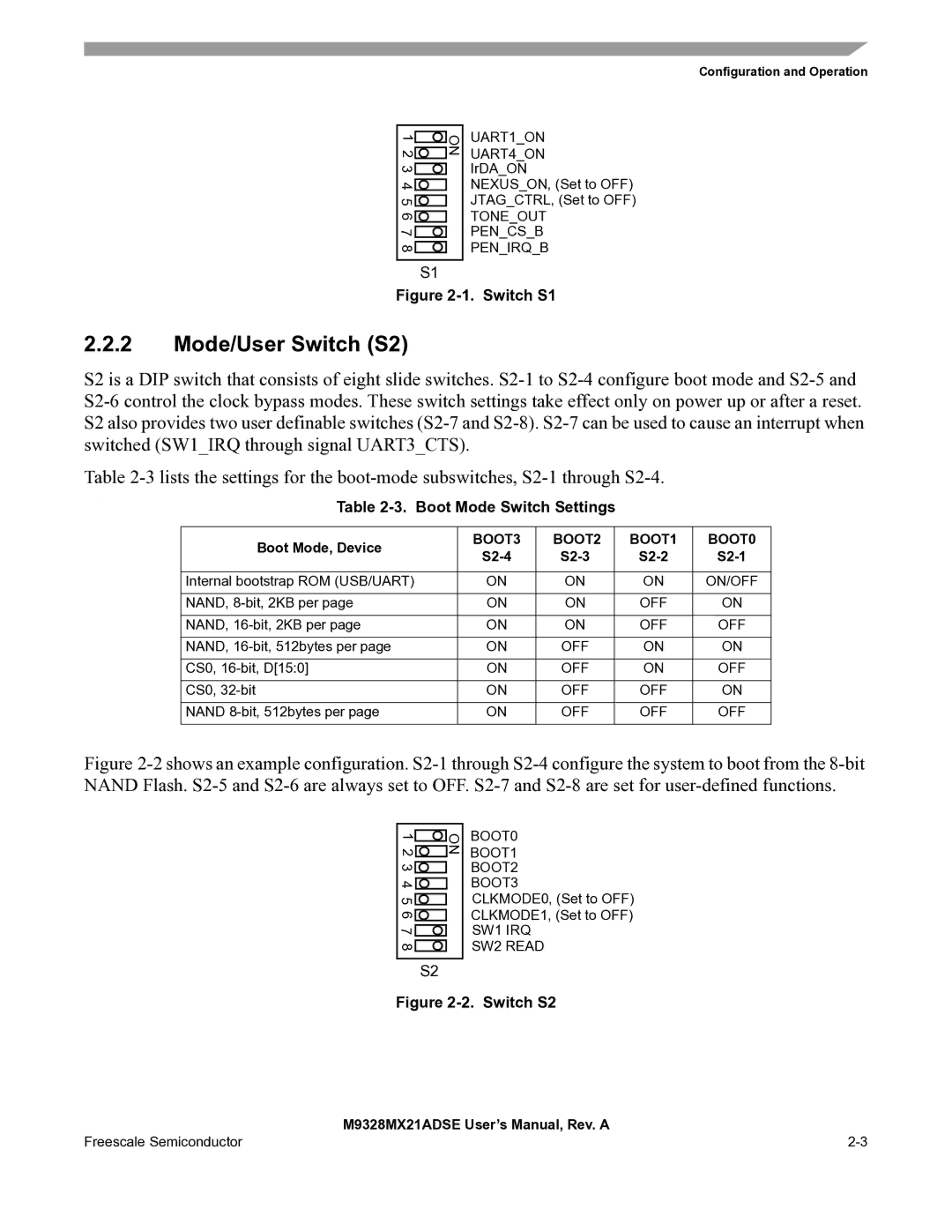
Figure 2-2 shows an example configuration. S2-1 through S2-4 configure the system to boot from the 8-bit NAND Flash. S2-5 and S2-6 are always set to OFF. S2-7 and S2-8 are set for user-defined functions.
1 2 |
|
|
| ON |
|
|
| ||
|
|
| ||
|
|
| ||
3 |
|
|
|
|
|
|
|
| |
4 |
|
| ||
|
| |||
5 6 |
|
|
| |
|
|
| ||
|
|
| ||
|
|
| ||
7 |
|
|
|
|
|
|
|
| |
|
|
| ||
8 |
|
|
| |
|
|
|
|
|
S2
BOOT0
BOOT1
BOOT2
BOOT3
CLKMODE0, (Set to OFF) CLKMODE1, (Set to OFF)
SW1 IRQ
SW2 READ
Figure 2-2. Switch S2
| M9328MX21ADSE User’s Manual, Rev. A |
Freescale Semiconductor |