Support Information
3.4UART/RS-232 Connectors
This section describes the DB9
3.4.1UART1 Connector
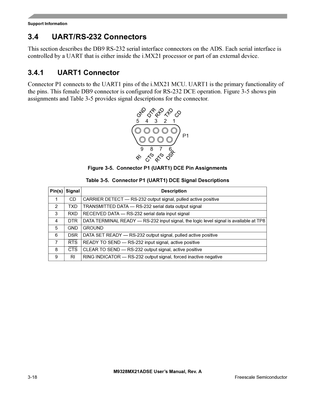
Connector P1 connects to the UART1 pins of the i.MX21 MCU. UART1 is the primary functionality of the pins. This female DB9 connector is configured for
G | N | D | D | T | R | R | X | D | T | X | D |
| C | D | |
|
|
|
|
| |||||||||||
|
|
|
|
|
|
|
|
|
| ||||||
5 |
|
| 4 |
|
| 3 |
|
| 2 |
|
| 1 |
| ||
|
|
|
|
|
|
|
|
|
|
|
|
|
|
|
|
| 9 |
| 8 |
| 7 | |
I |
| T | S |
| T | S |
R | C |
| R |
| ||
P1
| 6 | |
D | S | R |
| ||
|
| |
|
|
|
|
| Figure |
|
|
|
|
| Table |
|
|
| |||
Pin(s) | Signal | Description | |||
|
|
|
| ||
1 |
| CD | CARRIER DETECT — | ||
|
|
|
| ||
2 |
| TXD | TRANSMITTED DATA — | ||
|
|
| |||
3 | RXD | RECEIVED DATA — | |||
|
|
| |||
4 | DTR | DATA TERMINAL READY — | |||
|
|
| |||
5 | GND | GROUND | |||
|
|
| |||
6 | DSR | DATA SET READY — | |||
|
|
|
|
|
|
7 |
| RTS |
|
| READY TO SEND — |
8 |
| CTS |
| CLEAR TO SEND — | |
9 |
| RI | RING INDICATOR — | ||
|
|
|
|
|
|
| M9328MX21ADSE User’s Manual, Rev. A |
Freescale Semiconductor |