|
| Configuration and Operation | |
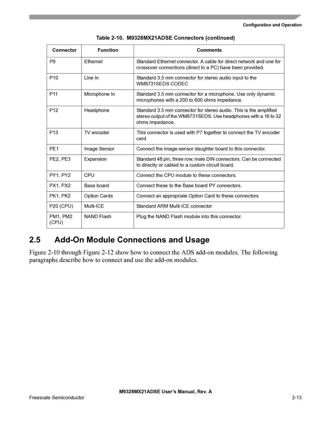
| Table | ||
|
|
|
|
Connector | Function | Comments |
|
|
|
|
|
P9 | Ethernet | Standard Ethernet connector. A cable for direct network and one for |
|
|
| crossover connections (direct to a PC) have been provided. |
|
|
|
|
|
P10 | Line In | Standard 3.5 mm connector for stereo audio input to the |
|
|
| WM8731SEDS CODEC |
|
|
|
|
|
P11 | Microphone In | Standard 3.5 mm connector for a microphone. Use only dynamic |
|
|
| microphones with a 200 to 600 ohms impedance. |
|
|
|
|
|
P12 | Headphone | Standard 3.5 mm connector for stereo audio. This is the amplified |
|
|
| stereo output of the WM8731SEDS. Use headphones with a 16 to 32 |
|
|
| ohms impedance. |
|
|
|
|
|
P13 | TV encoder | This connector is used with P7 together to connect the TV encoder |
|
|
| card. |
|
|
|
|
|
PE1 | Image Sensor | Connect the |
|
|
|
|
|
PE2, PE3 | Expansion | Standard 48 pin, three row, male DIN connectors. Can be connected |
|
|
| to directly or cabled to a custom circuit board. |
|
|
|
|
|
PY1, PY2 | CPU | Connect the CPU module to these connectors. |
|
|
|
|
|
PX1, PX2 | Base board | Connect these to the Base board PY connectors. |
|
|
|
|
|
PK1, PK2 | Option Cards | Connect an appropriate Option Card to these connectors |
|
|
|
|
|
P20 (CPU) | Standard ARM |
| |
|
|
|
|
PM1, PM2 | NAND Flash | Plug the NAND Flash module into this connector. |
|
(CPU) |
|
|
|
|
|
|
|
2.5Add-On Module Connections and Usage
Figure 2-10 through Figure 2-12 show how to connect the ADS add-on modules. The following paragraphs describe how to connect and use the add-on modules.
| M9328MX21ADSE User’s Manual, Rev. A |
Freescale Semiconductor |