Configuration and Operation
i.MX21
BA1..3
D0..15
CS_LAN
B_OE
B_RW B_DQM3_EB3 UART3_RTS
VCC |
|
|
|
|
|
|
|
| |
SA8 |
| Isolation | ||||||
SA9 |
| |||||||
| Transformer | |||||||
SA0 |
| |||||||
|
|
|
|
|
| P9 | ||
|
|
| ||||||
SA4..7 |
|
|
|
|
|
|
|
|
SA10..19 |
|
|
|
|
|
|
|
|
|
|
|
|
|
|
|
| |
|
|
|
|
|
|
|
|
|
SA1..3 |
|
|
|
|
| RJ45 Connector | ||
|
|
|
|
|
|
|
| |
D0..15 |
|
|
|
|
|
|
|
|
AEN
IOR
IOW
SBHE
INTRQ0
CHIPSEL
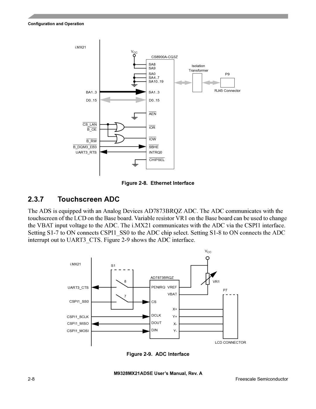
Figure 2-8. Ethernet Interface
2.3.7Touchscreen ADC
The ADS is equipped with an Analog Devices AD7873BRQZ ADC. The ADC communicates with the touchscreen of the LCD on the Base board. Variable resistor VR1 on the Base board can be used to change the VBAT input voltage to the ADC. The i.MX21 communicates with the ADC via the CSPI1 interface. Setting
i.MX21 | S1 |
|
|
| |
| AD7873BRQZ | |
| 8 |
|
UART3_CTS | PENIRQ VREF | |
| 7 | VBAT |
|
| |
CSPI1_SS0 | CS |
|
|
| X+ |
CSPI1_SCLK | DCLK | Y+ |
CSPI1_MISO | DOUT | X- |
CSPI1_MOSI | DIN | Y- |
VCC
![]() VR1
VR1
P7
LCD CONNECTOR
Figure 2-9. ADC Interface
| M9328MX21ADSE User’s Manual, Rev. A |
Freescale Semiconductor |