Support Information
3.3CPU to Option Card Connectors
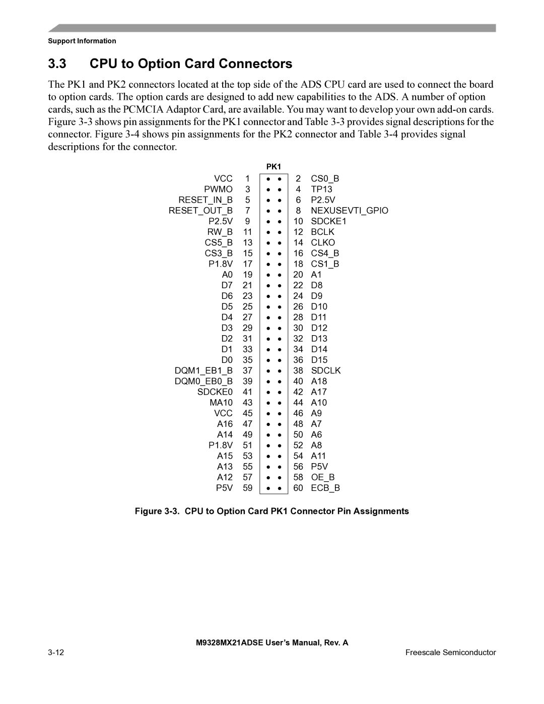
The PK1 and PK2 connectors located at the top side of the ADS CPU card are used to connect the board to option cards. The option cards are designed to add new capabilities to the ADS. A number of option cards, such as the PCMCIA Adaptor Card, are available. You may want to develop your own
PK1
VCC 1 • • PWMO 3 • • RESET_IN_B 5 • • RESET_OUT_B 7 • • P2.5V 9 • • RW_B 11 • • CS5_B 13 • • CS3_B 15 • • P1.8V 17 • • A0 19 • • D7 21 • • D6 23 • • D5 25 • • D4 27 • • D3 29 • • D2 31 • • D1 33 • • D0 35 • •
DQM1_EB1_B 37 • • DQM0_EB0_B 39 • • SDCKE0 41 • • MA10 43 • • VCC 45 • • A16 47 • • A14 49 • • P1.8V 51 • • A15 53 • • A13 55 • • A12 57 • • P5V 59 • •
2CS0_B
4TP13
6P2.5V
8NEXUSEVTI_GPIO
10SDCKE1
12BCLK
14CLKO
16CS4_B
18CS1_B
20A1
22D8
24D9
26D10
28D11
30D12
32D13
34D14
36D15
38SDCLK
40A18
42A17
44A10
46A9
48A7
50A6
52A8
54A11
56P5V
58OE_B
60ECB_B
Figure 3-3. CPU to Option Card PK1 Connector Pin Assignments
| M9328MX21ADSE User’s Manual, Rev. A |
Freescale Semiconductor |