Support Information
3.4.3External UART Connector
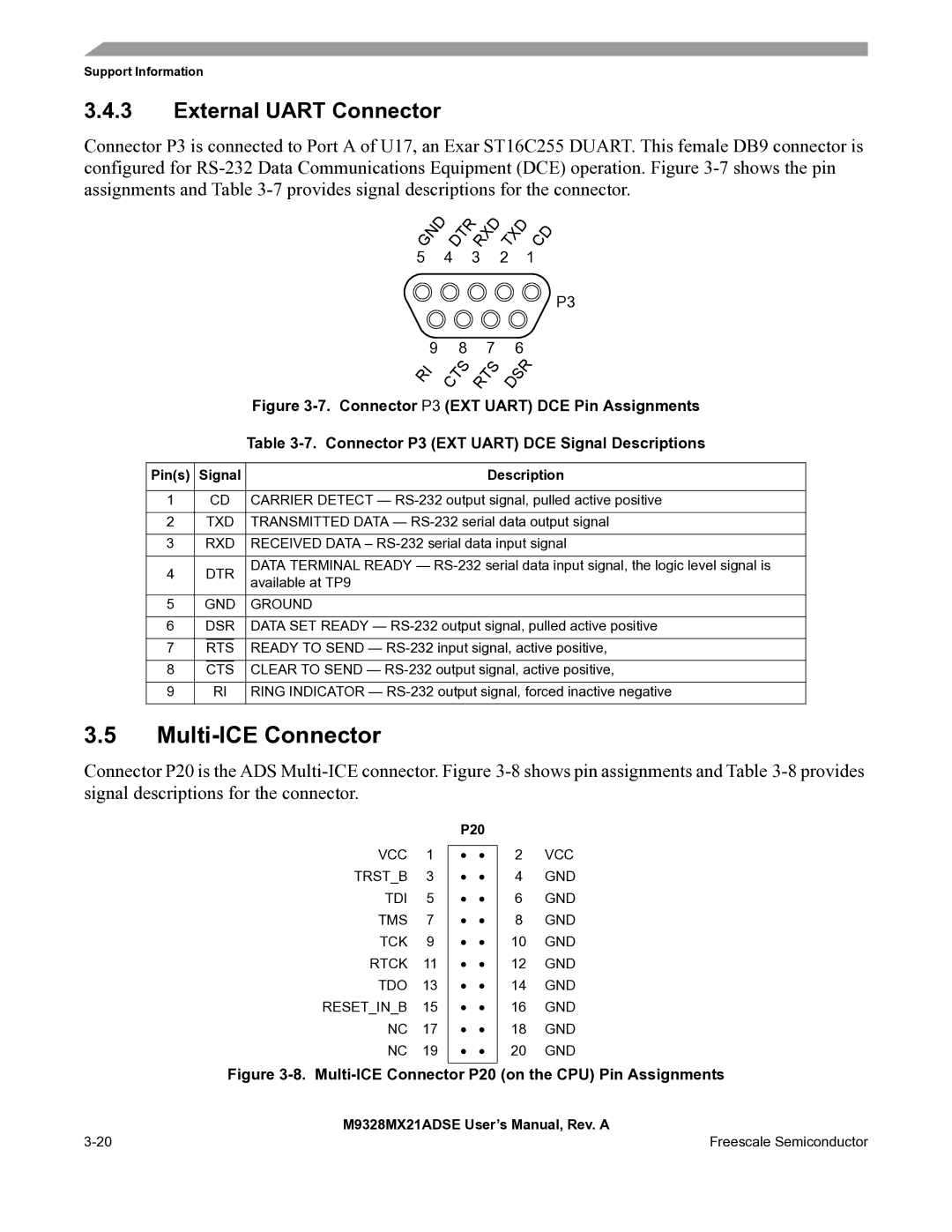
Connector P3 is connected to Port A of U17, an Exar ST16C255 DUART. This female DB9 connector is configured for
|
|
|
|
| G | N | D | D | T | R | R | X | D | T | X | D |
| C | D | |||||
|
|
|
|
|
|
|
|
|
|
|
| |||||||||||||
|
|
|
|
|
|
|
|
|
|
|
|
|
|
|
|
|
| |||||||
|
|
|
|
| 5 |
|
| 4 |
|
|
| 3 |
|
| 2 |
|
|
|
|
| 1 |
| ||
|
|
|
|
|
|
|
|
|
|
|
|
|
|
|
|
|
|
|
|
|
|
|
| P3 |
|
|
|
|
|
|
|
|
|
|
|
|
|
|
|
|
|
|
|
|
| ||||
|
|
|
|
|
|
| 9 |
|
| 8 |
| 7 |
|
| 6 |
|
|
| ||||||
|
|
|
|
|
| I |
|
| T | S |
| T | S |
|
| S | R |
| ||||||
|
|
|
|
| R |
|
| C |
|
| R |
| D |
|
|
|
| |||||||
|
|
|
|
| Figure | |||||||||||||||||||
|
|
|
|
| Table | |||||||||||||||||||
|
|
|
|
|
|
|
|
|
|
|
|
|
| |||||||||||
Pin(s) | Signal |
|
|
|
|
|
|
|
|
| Description | |||||||||||||
|
|
|
|
|
|
|
| |||||||||||||||||
1 |
| CD | CARRIER DETECT — | |||||||||||||||||||||
|
|
|
|
|
|
|
| |||||||||||||||||
2 |
| TXD | TRANSMITTED DATA — | |||||||||||||||||||||
|
|
|
|
|
|
| ||||||||||||||||||
3 | RXD | RECEIVED DATA – | ||||||||||||||||||||||
|
|
|
|
|
|
|
|
|
| |||||||||||||||
4 | DTR | DATA TERMINAL READY — | ||||||||||||||||||||||
available at TP9 |
|
|
|
|
|
|
|
|
|
|
|
|
|
|
|
|
|
| ||||||
|
|
|
|
|
|
|
|
|
|
|
|
|
|
|
|
|
|
|
|
|
|
| ||
|
|
|
|
|
|
|
|
|
|
|
|
|
|
|
|
|
|
|
|
|
| |||
5 | GND | GROUND |
|
|
|
|
|
|
|
|
|
|
|
|
|
|
|
|
|
| ||||
|
|
|
|
|
|
| ||||||||||||||||||
6 | DSR | DATA SET READY — | ||||||||||||||||||||||
|
|
|
|
|
|
|
|
|
| |||||||||||||||
7 |
| RTS |
|
| READY TO SEND — | |||||||||||||||||||
|
|
|
|
|
|
|
|
| ||||||||||||||||
8 |
| CTS |
| CLEAR TO SEND — | ||||||||||||||||||||
9 |
| RI | RING INDICATOR — | |||||||||||||||||||||
|
|
|
|
|
|
|
|
|
|
|
|
|
|
|
|
|
|
|
|
|
|
|
|
|
3.5Multi-ICE Connector
Connector P20 is the ADS
VCC 1 TRST_B 3 TDI 5 TMS 7 TCK 9 RTCK 11 TDO 13
RESET_IN_B 15 NC 17 NC 19
P20
• •
• •
• •
• •
• •
• •
• •
• •
• •
• •
2VCC
4GND
6GND
8GND
10 GND
12 GND
14 GND
16 GND
18 GND
20 GND
Figure 3-8. Multi-ICE Connector P20 (on the CPU) Pin Assignments
| M9328MX21ADSE User’s Manual, Rev. A |
Freescale Semiconductor |